GE
D
IRECTION
5573152-100, R
EV
. 2
LOGIQ E9 S
ERVICE
M
ANUAL
Chapter 8 Replacement procedures
8 - 215
8-9-3-2
BEP installation
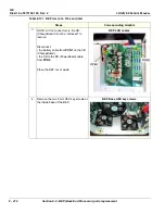
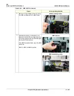
Table 8-132 BEP installation
Steps
Corresponding Graphic
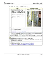
1.
Disconnect:
• the battery cable from
PCN1
.
• the CB to PB cable from
PCN2
.
Place the BEP cover aside.
BEP6 CB cables
2.
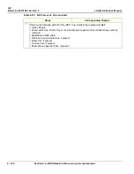
Re-install the following parts into the replacement BEP:
• Option Dongle
• Printer Tray and/or the Printer or the Shear Wave Capacitor Pack if Shear Wave option was
installed.
• BackPlane to BEP cable
• Wireless Card and Antennas, if present
• Patient I/O, if present
• S Video Card, if present
• Shear Wave Capacitor Pack
3.
Slide the BEP into the left side of the chassis frame.
4.
Install the two HEX key screws at the inside
base of the BEP (Torque: 10 Nm
{7.4 lbf-ft}).
Содержание LOGIQ E9
Страница 1: ...12 13 18 GEHC_FRNT_CVR FM LOGIQ E9 SERVICE MANUAL VERSION R6 Part Number 5573152 100 Revision Rev 2 ...
Страница 2: ......
Страница 11: ...GE DIRECTION 5573152 100 REV 2 LOGIQ E9 SERVICE MANUAL xi ZH CN KO ...
Страница 140: ...DIRECTION 5573152 100 REV 2 LOGIQ E9 SERVICE MANUAL 4 50 Section 4 8 Site Log This page was intentionally left blank ...
Страница 753: ......
Страница 754: ......

