GE
D
IRECTION
5573152-100, R
EV
. 2
LOGIQ E9 S
ERVICE
M
ANUAL
Chapter 8 Replacement procedures
8 - 141
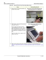
4.
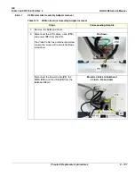
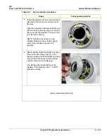
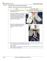
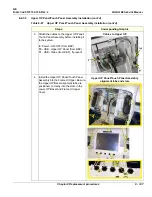
Remove the four screws with washers from
the rear of the console.
Back Cover of the Upper OP Panel/Touch
Panel Assembly, Screws and Washers
5.
NOTE: Make sure the five OP Panel Knobs
have been removed.
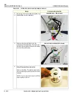
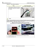
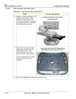
Lift the Upper OP Panel/Touch Panel
assembly slightly from the bottom, and then
tilt the top toward the front of the system.
There are tabs at the bottom of the Touch
Panel Assembly. Pull straight up on these
tabs.
NOTE: For better access, swing the LCD
Monitor to the side.
Removing the Upper OP Panel/Touch
Panel Assembly
6.
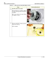
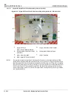
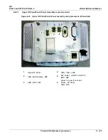
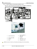
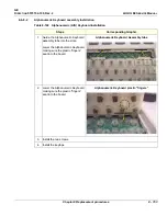
Disconnect the cables at the back of the Upper OP Panel/Touch Panel Assembly (see:
Figure 8-32 "Upper OP Panel/Touch Panel assembly cable placement - R4 and earlier" on page
8-142
).
Table 8-95 Upper OP Panel/Touch Panel Assembly removal
Steps
Corresponding Graphic
Содержание LOGIQ E9
Страница 1: ...12 13 18 GEHC_FRNT_CVR FM LOGIQ E9 SERVICE MANUAL VERSION R6 Part Number 5573152 100 Revision Rev 2 ...
Страница 2: ......
Страница 11: ...GE DIRECTION 5573152 100 REV 2 LOGIQ E9 SERVICE MANUAL xi ZH CN KO ...
Страница 140: ...DIRECTION 5573152 100 REV 2 LOGIQ E9 SERVICE MANUAL 4 50 Section 4 8 Site Log This page was intentionally left blank ...
Страница 753: ......
Страница 754: ......

