9-
53
9
T
roubleshooting
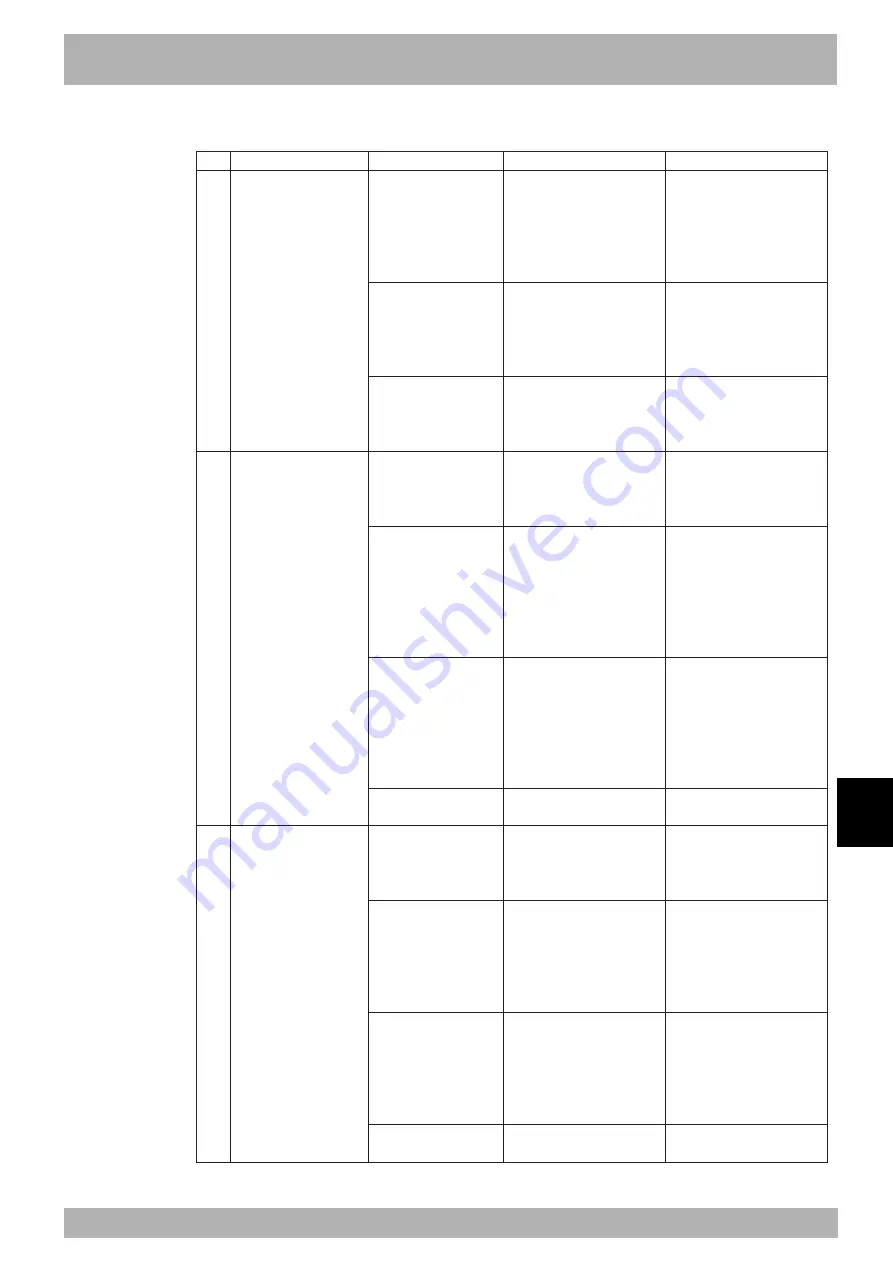
2. Troubleshooting
2. Robot operation
1
2
3
Symptom
Controller turns on but
can't execute program and
manual movement.
Abnormal sound or
vibration.
Position deviation
occurred.
• There are 2 main types of
position deviation.
1. Electrical position
deviation
2. Mechanical position
deviation
In case 1, if position
deviation occurs, you
can perform return-to-
origin and return to
original position. In
case 2, you cannot
return to original
position.
Possible cause
• Interlock signal.
• Robot is in emergency
stop.
• Error occurred.
• Wrong robot or axis type
setting.
• Tip weight/ acceleration
settings are incorrect.
• Mechanical problem
occurred.
• Controller is defective.
• Position sensor device is
defective.
• Cable is defective.
• Position detection error
due to noise.
• Mechanical error
occurred.
• Controller is defective.
Corrective action
• Connect the standard I/O
interface connector for
interlock signal.
• Connect the DC 24V power supply.
• Disable interlock signal with
the parameter.
• Release MPB emergency stop
switch.
• Plug in MPB connector.
• Connect MPB emergency stop
terminal of SAFETY connector.
• Check the cause from the
error information.
• Eliminate the cause of the
error.
• Change to correct robot or axis
type setting.
• Make sure robot and controller
are compatible.
• Set a correct tip weight
parameter
• Set a correct “Accel.
Coefficient” parameter.
• Make a correct setting in the
program language.
• Reinforce the robot frame.
• Tighten the robot cover
screws.
• Remove foreign matter if
found.
• Replace if warped or damaged
guides or ball screws are found.
• If operation is normal use the
substitute controller.
• Replace motor if count is
incorrect.
• Replace cable if found to be
defective.
• Ground the robot and
controller.
• Isolate from noise sources
around robot.
• Isolate from noise sources
around robot I/O cable.
• Adjust to correct tension if
necessary.
• Remove foreign matter if
found.
• Replace guides or ball screws
if warping or damage is found.
• If operation is normal use the
substitute controller.
Check items
• Check standard I/O interface
connector (for interlock signal)
and check if DC 24V is
supplied.
• Check DI11 on MPB screen.
• Connect the MPB and check
error. information.
• Check DI00 on MPB screen.
• Connect the MPB and check
error info
• Check if “ERR” LED on front
panel is lit.
• Connect MPB and check robot
settings in SYSTEM mode.
• Check if robot and controller
are compatible.
• Check tip weight parameter
setting in SYSTEM mode.
• Check “Accel. Coefficient”
parameter setting in SYSTEM
mode.
• Check AXWGHT/ACCEL
commands in program language.
• Check for resonance in robot
frame.
• Check for loose screws on
robot cover.
• Check for warping or damage
on guides or ball screws.
• Replace with another
controller and check operation.
• Move axis in emergency stop
and check the pulse count.
• Check grounding of robot and
controller.
• Check robot periphery for
noise.
• Check for noise sources
around robot I/O cable.
• Check the belt tension
• Check for warping or damage
on guides or ball screws.
• Replace with another
controller and check operation.
Summary of Contents for RCX141
Page 1: ...User s Manual ENGLISH E YAMAHA 4 AXIS ROBOT CONTROLLER E93 Ver 2 02 RCX141 ...
Page 2: ......
Page 16: ...viii MEMO ...
Page 18: ...MEMO ...
Page 24: ...1 6 MEMO ...
Page 26: ...MEMO ...
Page 34: ...2 8 MEMO ...
Page 36: ...MEMO ...
Page 54: ...3 18 MEMO ...
Page 290: ...4 232 MEMO ...
Page 292: ...MEMO ...
Page 316: ...5 24 MEMO ...
Page 318: ...MEMO ...
Page 326: ...6 8 MEMO ...
Page 328: ...MEMO ...
Page 338: ...7 10 MEMO ...
Page 340: ...MEMO ...
Page 346: ...MEMO ...
Page 401: ...MEMO ...


