


Communication / CBC CANopen Communication Board
02.2004
6SE7087-6QX70 (Version AD) Siemens AG
8.5-82
Compendium Motion Control SIMOVERT MASTERDRIVES
Homing methods using P178 = 16 or 18 and P647.01 = 4 or
P648.01 = 4
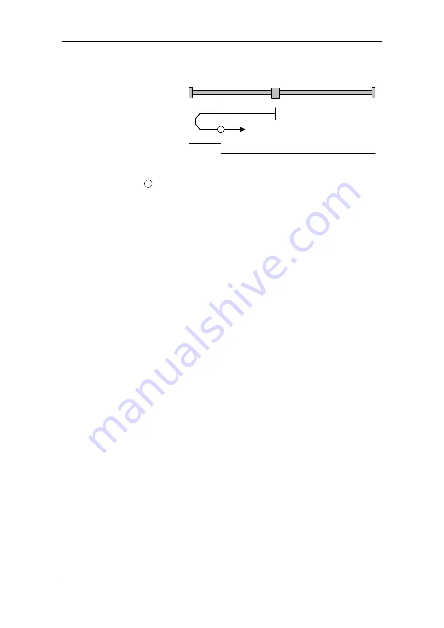
17
Negative Limit Switch
Fig. 8.5-10
Homing_method 17
17
Axis is positioned to the right of the BERO installed as a negative
limit switch. The homing operation is started by bit 4 in the control word.
Behavior of MASTERDRIVES MC with F01
The axis traverses under speed control at homing approach velocity v
A
[MD7] towards the Bero. When the Bero responds, the axis decelerates
down to homing creep velocity v
R
[MD6] and changes its direction of
rotation. When the Bero falling edge appears, the axis is decelerated
down to standstill under speed control. It retraces the deceleration path
traveled as a result of the braking operation by executing a position-
controlled return motion (positioning) towards the zero pulse. The axis
then activates "Homing Attained" in the status word via bit ARFD.
Behavior of MASTERDRIVES MC without F01
The axis traverses under position control towards the Bero at the
values stored in U006 (homing acceleration) and U873.01 (homing
speed). When the Bero responds, the axis changes its direction of
rotation and travels at the same speed in the opposite direction. When
the Bero falling edge appears, the axis is decelerated to a standstill with
the value from U006. It does not retrace the braking path traveled
during the braking operation. It activates "Homing Attained" in the
status word via bit ARFD.
Homing_method 17


