Contents
12.2010
Siemens AG
6SE7087-6QX70 (Version AM)
SIMOVERT MASTERDRIVES
Compendium Motion Control
1
Contents
1
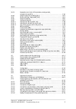
SYSTEM DESCRIPTION ................................................................................. 1-1
1.1
Overview........................................................................................................... 1-1
1.2
System description ........................................................................................... 1-2
1.3
Construction sizes ............................................................................................ 1-3
1.4
Communication................................................................................................. 1-4
2
CONFIGURATION AND CONNECTION EXAMPLES .................................... 2-1
2.1
Compact PLUS type units ................................................................................ 2-1
2.1.1
Single-axis drive ............................................................................................... 2-1
2.1.2
Multi-axis drive up to 3 axes ............................................................................. 2-1
2.1.3
Multi-axis drive.................................................................................................. 2-2
2.1.4
Configuration and connection examples (Compact PLUS).............................. 2-5
2.2
Compact and chassis-type units ...................................................................... 2-9
2.2.1
Water-cooled units............................................................................................ 2-9
2.2.2
Single-axis drive with Compact or chassis-type units ...................................... 2-9
2.2.3
Multi-axis drive with Compact or chassis-type units......................................... 2-9
2.2.4
Explanations relating to the configuration examples
(Compact and chassis-type units) .................................................................. 2-13
2.3
Points to look out for when using certain option boards and CUPM.............. 2-16
2.3.1
Encoder interface connections ....................................................................... 2-16
2.3.2
TB boards ....................................................................................................... 2-17
2.3.3
EB boards ....................................................................................................... 2-17
2.4
Safe stop functions of electrical drive systems in accordance with
DIN EN 61800-5-2 .......................................................................................... 2-18
2.4.1
Reference documents .................................................................................... 2-18
2.4.2
Overview......................................................................................................... 2-19
2.4.2.1
Safety function STO – Safe Torque Off.......................................................... 2-19
2.4.2.2
Safety function SS1 – Safe Stop 1 (time controlled) ...................................... 2-19
2.4.3
General information about MASTERDRIVES ................................................ 2-20
2.4.4
Safety functions .............................................................................................. 2-23
2.4.4.1
STO principle in a safety function................................................................... 2-24
2.4.4.2
SS1 principle in a safety function ................................................................... 2-25
2.4.5
Application examples...................................................................................... 2-26
2.4.5.1
Emergency Stop on a converter
→
STO........................................................ 2-26
2.4.5.2
Measures against common cause failure (CCF) of the safety function ......... 2-31
2.4.5.3
Check of the PFH value of the safety function as a whole............................. 2-32
2.4.6
Emergency Stop and protective door monitoring on a converter
→
STO...... 2-32
2.4.6.1
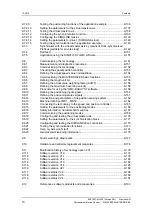
Protective door safety function ....................................................................... 2-35
2.4.6.2
Supplementary safety function Emergency Stop ........................................... 2-40


