

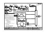


Function diagram
8
7
6
5
4
3
2
1
fp_mc_839e_e.vsd
Technology option
MASTERDRIVES MC
01.07.03
Mode of Operation Synchronism - Cam with max. 8 tables in variable configurations
- 839e -
(for sheet [834] ...[843])
see [331.3]
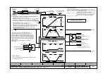
Status of the table last checked
0 = No error
1 = Number of support points = 0
2 = Support value > Table width
3 = Ascending sequence of support
values for X axis violated
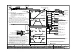
Table 1
Y
X
1
2
3
4
Y1
Y2
Y3
Y4
X1 X2 X3 X4
X_max
Relative
(U616=xxx1)
Absolute
(U616=xxx0)
U620, U629
Cam
Table 2
Table info
First index = start of table
Second index = end of table
Table 1 = Index 1,2
Table 5 = Index 9,10
Table 2 = Index 3,4
Table 6 = Index 11,12
Table 3 = Index 5,6
Table 7 = Index 13,14
Table 4 = Index 7,8
Table 8 = Index 15,16
1...50 = Index .01 ... .50 of the
last error-free support
values
1 = U630 defective
2 = U631 defective
3 = U640 defective
4 = U641 defective
5 = U632 defective
6 = U633 defective
7 = U642 defective
8 = U643 defective
T H Z E
[TABLE_NO] 0 = Table 1
1 = Table 2
2 = Table 3
3 = Table 4
4 = Table 5
5 = Table 6
6 = Table 7
7 = Table 8
Table 3
Table 4
0
7
6
5
4
3
2
1
2 2 2
2
1
0
Y
Cam
output
[835.4]
Support points, Y axis:
-2
31
... 2
31
-1 LU
Status, table
[836.1]
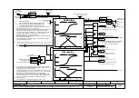
Cam input
<2>
1...50 = Index .01 ... .50
1...8 = Parameter numbers U630...U643
X H Z E
X
<2>
<1>
n668.x
<1> U617.x = 0 : Table OK
U617.x = 1 : Table has been changed and not yet checked or
the check found an error (error status in n668.x)
U617.x = 2 : Check command for table; if the table is OK,
the value "0" is automatically entered in U617as an ack-
nowledgement; if the table is not OK, U617 jumps back
to the value "1"
U617.x =10:
Table not present
<2> Can only be changed when curve cam is not selected
<3> Variable table configuration:
By means of 629.1-8 (number of support points) a total of 400 points
can be variably assigned. The support points still free are shown
in n661. The starting and ending indexes of each table, indicating
where the tables are entered, are given in n660.1-16.
Table configuration
0 = One table with 400 points (Table 1 {X1-X400})
1 = Two tables with 200 points each (Tables 1 {X1-X200} and 2 {X201-X400})
2 = Four tables with 100 points each (Tables 1, 2, 3, and 4)
3 = Eight tables with 50 points each (Tables 1 ... 8)
4 = Variable with up to 8 tables with a total of 400 support values
<2>
<2>
Table 5
Table 6
Table 7
Table 8
<2>
Support points, X axis:
0 ... 2
31
-1 LU
<2>
V2.5
U953.33 = ___(20)
KK0845
Status, table 8
KK0810
Status, table 1
KK0811
Status, table 2
KK0840
Status, table 3
KK0841
Status, table 4
KK0842
Status, table 5
KK0843
Status, table 6
KK0844
Status, table 7
No. of free
support points
n634
Table info
n639.1...16
B
U650 (0)
.01
B
.02
B
.03
U615. (1) = 4
Table width X_max
0...2
31
-1 LU
U620.01 (4096) for Table 1
U620.02 (4096) for Table 2
U620.03 (4096) for Table 3
U620.04 (4096) for Table 4
U620.05 (4096) for Table 5
U620.06 (4096) for Table 6
U620.07 (4096) for Table 7
U620.08 (4096) for Table 8
Number of support points X_max 1...400
U629.1 (0) = Table 1
U629.2 (0) = Table 2
U629.3 (0) = Table 3
U629.4 (0) = Table 4
U629.5 (0) = Table 5
U629.6 (0) = Table 6
U629.7 (0) = Table 7
U629.8 (0) = Table 8
Check table 0...2
U617.01 Table 1
U617.02 Table 2
U617.03 Table 3
U617.04 Table 4
U617.05 Table 5
U617.06 Table 6
U617.07 Table 7
U617.08 Table 8
n668.1
n668.2
n668.3
n668.4
n668.5
n668.6
n668.7
n668.8
X1-X50
X351-X400
X301-X350
X251-X300
X201-X250
X151-X200
X101-X150
X51-X100
U642.1-50
U630.1-50
U640.1-50
U641.1-50
U632.1-50
U633.1-50
U643.1-50
U631.1-50
Y1-Y50
Y51-Y100
Y101-Y150
Y151-Y200
Y201-Y250
Y251-Y300
Y301-Y350
Y351-Y400
U648.1-50
U636.1-50
U645.1-50
U646.1-50
U637.1-50
U638.1-50
U647.1-50
U635.1-50
Current table number 1...8
n644


