If you have a…
Then…
FAS2600 series and FAS2700 single-path HA
configuration
Give back the target node:
storage failover
giveback -fromnode partner_HA_node
FAS2600 series single-path configuration
Reboot your system.
13. Verify that the IOM12 module port links have been established.
For each module port that you cabled, the LNK (green) LED illuminates when one or more of the four SAS
lanes have established a link (with either an adapter or another disk shelf).
14. Return the failed part to NetApp, as described in the RMA instructions shipped with the kit.
Contact technical support at
, 888-463-8277 (North America), 00-800-44-638277 (Europe),
or +800-800-80-800 (Asia/Pacific) if you need the RMA number or additional help with the replacement
procedure.
Hot-swap a power supply - shelves with IOM12 modules
You can hot-swap a failed power supply in a DS460C, DS224C, or DS212C disk shelf.
Before you begin
All other components in the system—including the other power supply—must be functioning properly.
About this task
• If you are replacing more than one power supply, you must do so one at a time so that the disk shelf
maintains power.
• You must replace a power supply within two minutes of removal to minimize disruption to the disk shelf’s
airflow.
• Always use two hands when removing, installing, or carrying a power supply to support its weight.
• The best practice is to have the current versions of disk shelf (IOM) firmware and disk drive firmware on
your system before adding new disk shelves, shelf FRU components, or SAS cables.
Current versions of firmware can be found on the NetApp Support Site.
NetApp Downloads: Disk Shelf Firmware
NetApp Downloads: Disk Drive Firmware
• If needed, you can turn on the disk shelf’s location (blue) LEDs to aid in physically locating the affected disk
shelf:
storage shelf location-led modify -shelf-name
shelf_name
-led-status on
A disk shelf has three location LEDs: one on the operator display panel and one on each IOM12 module.
Location LEDs remain illuminated for 30 minutes. You can turn them off by entering the same command,
but using the off option.
• If needed, you can refer to the Monitoring disk shelf LEDs section for information about the meaning and
location of disk shelf LEDs on the operator display panel and FRU components.
Steps
1656
Summary of Contents for AFF A700
Page 4: ...AFF and FAS System Documentation 1...
Page 208: ...3 Close the controller module cover and tighten the thumbscrew 205...
Page 248: ...2 Close the controller module cover and tighten the thumbscrew 245...
Page 308: ...Power supply Cam handle release latch Power and Fault LEDs Cam handle 305...
Page 381: ...Power supply Cam handle release latch Power and Fault LEDs Cam handle 378...
Page 437: ...1 Locate the DIMMs on your controller module 434...
Page 605: ...602...
Page 1117: ...3 Close the controller module cover and tighten the thumbscrew 1114...
Page 1157: ...2 Close the controller module cover and tighten the thumbscrew 1154...
Page 1228: ...Power supply Cam handle release latch Power and Fault LEDs Cam handle 1225...
Page 1300: ...Power supply Cam handle release latch Power and Fault LEDs Cam handle 1297...
Page 1462: ...Installing SuperRail to round hole four post rack 1459...
Page 1602: ...1599...
Page 1630: ...1627...
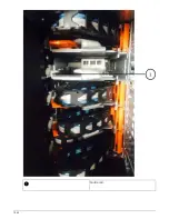
Page 1634: ...Orange ring on horizontal bracket Cable chain 1631...
Page 1645: ...Guide rail 1642...
Page 1669: ...Attention LED light on 1666...

