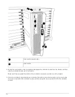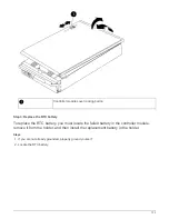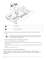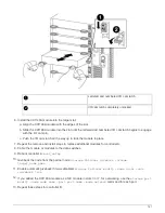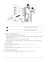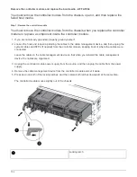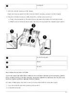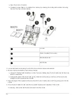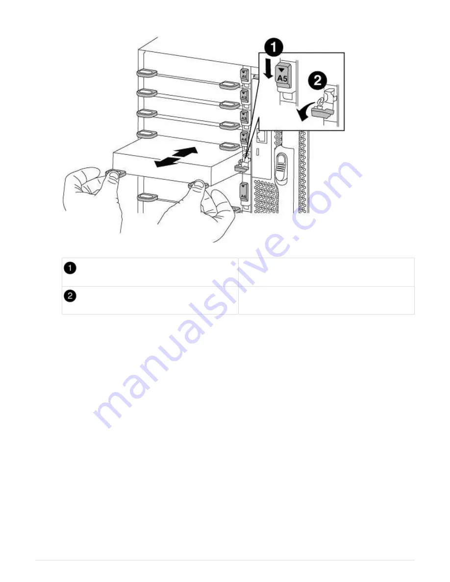
Lettered and numbered I/O cam latch
I/O cam latch completely unlocked
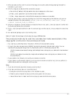
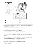
6. Install the X91148A module into slot 3:
a. Align the X91148A module with the edges of the slot.
b. Slide the X91148A module into the slot until the lettered and numbered I/O cam latch begins to engage
with the I/O cam pin.
c. Push the I/O cam latch all the way up to lock the module in place.
d. If you are installing a second X91148A module for storage, repeat the remove and install steps for the
module in slot 7.
7. Reboot controller A:
boot_ontap
8. Giveback the node from the partner node:
storage failover giveback -ofnode
target_node_name
9. Enable automatic giveback if it was disabled:
storage failover modify -node local -auto
-giveback true
10. Repeat these steps for controller B.
11. Install and cable your NS224 shelves, as described in
Hot-adding an NS224 drive shelf
743
Summary of Contents for AFF A700
Page 4: ...AFF and FAS System Documentation 1...
Page 208: ...3 Close the controller module cover and tighten the thumbscrew 205...
Page 248: ...2 Close the controller module cover and tighten the thumbscrew 245...
Page 308: ...Power supply Cam handle release latch Power and Fault LEDs Cam handle 305...
Page 381: ...Power supply Cam handle release latch Power and Fault LEDs Cam handle 378...
Page 437: ...1 Locate the DIMMs on your controller module 434...
Page 605: ...602...
Page 1117: ...3 Close the controller module cover and tighten the thumbscrew 1114...
Page 1157: ...2 Close the controller module cover and tighten the thumbscrew 1154...
Page 1228: ...Power supply Cam handle release latch Power and Fault LEDs Cam handle 1225...
Page 1300: ...Power supply Cam handle release latch Power and Fault LEDs Cam handle 1297...
Page 1462: ...Installing SuperRail to round hole four post rack 1459...
Page 1602: ...1599...
Page 1630: ...1627...
Page 1634: ...Orange ring on horizontal bracket Cable chain 1631...
Page 1645: ...Guide rail 1642...
Page 1669: ...Attention LED light on 1666...

