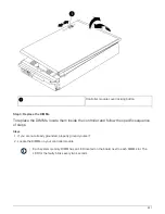

Step 4: Install the controller
After you install the components into the controller module, you must install the controller
module back into the system chassis and boot the operating system.
For HA pairs with two controller modules in the same chassis, the sequence in which you install the controller
module is especially important because it attempts to reboot as soon as you completely seat it in the chassis.
Steps
1. If you are not already grounded, properly ground yourself.
2. If you have not already done so, replace the cover on the controller module.
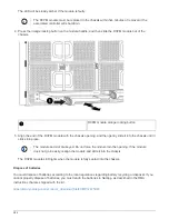
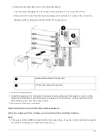
3. Align the end of the controller module with the opening in the chassis, and then gently push the controller
module halfway into the system.
Do not completely insert the controller module in the chassis until instructed to do so.
4. Cable the management and console ports only, so that you can access the system to perform the tasks in
the following sections.
You will connect the rest of the cables to the controller module later in this procedure.
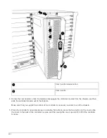
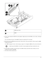
5. Complete the reinstallation of the controller module:
a. If you have not already done so, reinstall the cable management device.
b. Firmly push the controller module into the chassis until it meets the midplane and is fully seated.
The locking latches rise when the controller module is fully seated.
Do not use excessive force when sliding the controller module into the chassis to avoid
damaging the connectors.
The controller module begins to boot as soon as it is fully seated in the chassis. Be prepared to
interrupt the boot process.
c. Rotate the locking latches upward, tilting them so that they clear the locking pins, and then lower them
into the locked position.
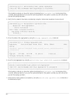
d. Interrupt the boot process by pressing
Ctrl-C
when you see
Press Ctrl-C for Boot Menu
.
e. Select the option to boot to Maintenance mode from the displayed menu.
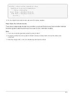
Step 5: Run system-level diagnostics
After installing a new DIMM, you should run diagnostics.
Your system must be at the LOADER prompt to start System Level Diagnostics.
All commands in the diagnostic procedures are issued from the node where the component is being replaced.
Steps
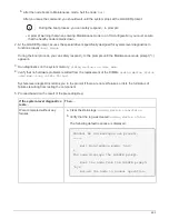
1. If the node to be serviced is not at the LOADER prompt, perform the following steps:
a. Select the Maintenance mode option from the displayed menu.
694
Summary of Contents for AFF A700
Page 4: ...AFF and FAS System Documentation 1...
Page 208: ...3 Close the controller module cover and tighten the thumbscrew 205...
Page 248: ...2 Close the controller module cover and tighten the thumbscrew 245...
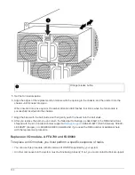
Page 308: ...Power supply Cam handle release latch Power and Fault LEDs Cam handle 305...
Page 381: ...Power supply Cam handle release latch Power and Fault LEDs Cam handle 378...
Page 437: ...1 Locate the DIMMs on your controller module 434...
Page 605: ...602...
Page 1117: ...3 Close the controller module cover and tighten the thumbscrew 1114...
Page 1157: ...2 Close the controller module cover and tighten the thumbscrew 1154...
Page 1228: ...Power supply Cam handle release latch Power and Fault LEDs Cam handle 1225...
Page 1300: ...Power supply Cam handle release latch Power and Fault LEDs Cam handle 1297...
Page 1462: ...Installing SuperRail to round hole four post rack 1459...
Page 1602: ...1599...
Page 1630: ...1627...
Page 1634: ...Orange ring on horizontal bracket Cable chain 1631...
Page 1645: ...Guide rail 1642...
Page 1669: ...Attention LED light on 1666...