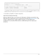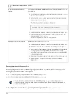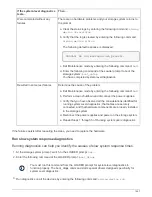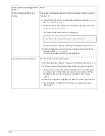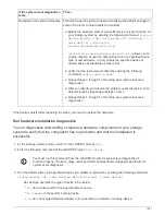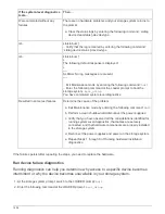
If the system-level diagnostics
tests…
Then…
Resulted in the same test failures
Technical support might recommend modifying the default settings on
some of the tests to help identify the problem.
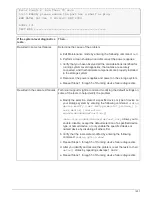
a. Modify the selection state of a specific device or type of device on
your storage system by entering the following command:
sldiag
device modify [-dev
devtype
|mb|slot_slotnum_] [-
name device] [-selection
enable|disable|default|only
]
-
selection
enable|disable|default|only
allows you to
enable, disable, accept the default selection of a specified device
type or named device, or only enable the specified device or
named device by disabling all others first.
b. Verify that the tests were modified by entering the following
command:
sldiag option show
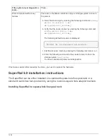
c. Repeat Steps 3 through 5 of
Running slow system response
diagnostics
.
d. After you identify and resolve the problem, reset the tests to their
default states by repeating substeps 1 and 2.
e. Repeat Steps 1 through 5 of
Running slow system response
diagnostics
.
If the failures persist after repeating the steps, you need to replace the hardware.
Run hardware installation diagnostics
You run diagnostics after adding or replacing hardware components in your storage
system to verify that the component has no problems and that the installation is
successful.
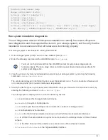
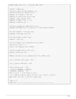
1. At the storage system prompt, switch to the LOADER prompt:
halt
2. Enter the following command at the LOADER prompt:
boot_diags
You must run this command from the LOADER prompt for system-level diagnostics to
function properly. The boot_diags command starts special drivers designed specifically for
system-level diagnostics.
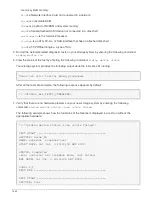
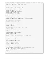
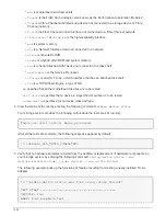
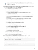
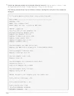
3. Run the default tests on the particular device you added or replaced by entering the following command:
sldiag device run [-dev devtype|mb|slotslotnum] [-name
device
]
◦
-dev devtype specifies the type of device to be tested.
▪
ata
is an Advanced Technology Attachment device.
▪
bootmedia
is the system booting device..
▪
cna
is a Converged Network Adapter not connected to a network or storage device.
1451
Summary of Contents for AFF A700
Page 4: ...AFF and FAS System Documentation 1...
Page 208: ...3 Close the controller module cover and tighten the thumbscrew 205...
Page 248: ...2 Close the controller module cover and tighten the thumbscrew 245...
Page 308: ...Power supply Cam handle release latch Power and Fault LEDs Cam handle 305...
Page 381: ...Power supply Cam handle release latch Power and Fault LEDs Cam handle 378...
Page 437: ...1 Locate the DIMMs on your controller module 434...
Page 605: ...602...
Page 1117: ...3 Close the controller module cover and tighten the thumbscrew 1114...
Page 1157: ...2 Close the controller module cover and tighten the thumbscrew 1154...
Page 1228: ...Power supply Cam handle release latch Power and Fault LEDs Cam handle 1225...
Page 1300: ...Power supply Cam handle release latch Power and Fault LEDs Cam handle 1297...
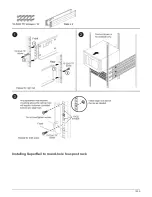
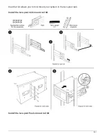
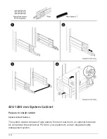
Page 1462: ...Installing SuperRail to round hole four post rack 1459...
Page 1602: ...1599...
Page 1630: ...1627...
Page 1634: ...Orange ring on horizontal bracket Cable chain 1631...
Page 1645: ...Guide rail 1642...
Page 1669: ...Attention LED light on 1666...

