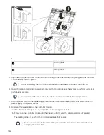
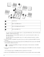
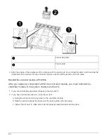
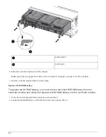

squarely into the slot.
The DIMM fits tightly in the slot, but should go in easily. If not, realign the DIMM with the slot and reinsert it.
Visually inspect the DIMM to verify that it is evenly aligned and fully inserted into the slot.
7. Push carefully, but firmly, on the top edge of the DIMM until the ejector tabs snap into place over the
notches at the ends of the DIMM.
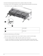
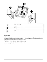
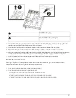
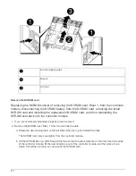
8. Reinstall any risers that you removed from the controller module.
If you removed the NVRAM riser, Riser 1, make sure that you plug the NVRAM battery into the controller
module.
9. Close the air duct.
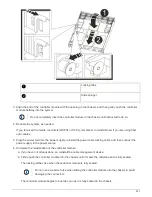
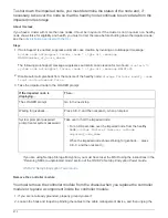
Reinstall the controller module and booting the system
After you replace a FRU in the controller module, you must reinstall the controller module
and reboot it.
For HA pairs with two controller modules in the same chassis, the sequence in which you install the controller
module is especially important because it attempts to reboot as soon as you completely seat it in the chassis.
1. If you are not already grounded, properly ground yourself.
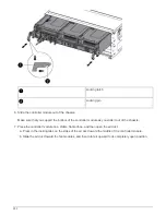
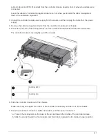
2. Align the end of the controller module with the opening in the chassis, and then gently push the controller
module halfway into the system.
Do not completely insert the controller module in the chassis until instructed to do so.
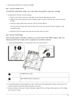
3. Recable the system, as needed.
If you removed the media converters (QSFPs or SFPs), remember to reinstall them if you are using fiber
optic cables.
4. Plug the power cord into the power supply, reinstall the power cable locking collar, and then connect the
power supply to the power source.
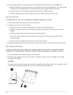
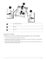
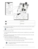
5. Complete the reinstallation of the controller module:
a. If you have not already done so, reinstall the cable management device.
b. Firmly push the controller module into the chassis until it meets the midplane and is fully seated.
The locking latches rise when the controller module is fully seated.
Do not use excessive force when sliding the controller module into the chassis to avoid
damaging the connectors.
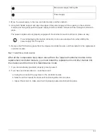
The controller module begins to boot as soon as it is fully seated in the chassis. Be prepared to
interrupt the boot process.
c. Rotate the locking latches upward, tilting them so that they clear the locking pins, and then lower them
into the locked position.
797
Summary of Contents for AFF A700
Page 4: ...AFF and FAS System Documentation 1...
Page 208: ...3 Close the controller module cover and tighten the thumbscrew 205...
Page 248: ...2 Close the controller module cover and tighten the thumbscrew 245...
Page 308: ...Power supply Cam handle release latch Power and Fault LEDs Cam handle 305...
Page 381: ...Power supply Cam handle release latch Power and Fault LEDs Cam handle 378...
Page 437: ...1 Locate the DIMMs on your controller module 434...
Page 605: ...602...
Page 1117: ...3 Close the controller module cover and tighten the thumbscrew 1114...
Page 1157: ...2 Close the controller module cover and tighten the thumbscrew 1154...
Page 1228: ...Power supply Cam handle release latch Power and Fault LEDs Cam handle 1225...
Page 1300: ...Power supply Cam handle release latch Power and Fault LEDs Cam handle 1297...
Page 1462: ...Installing SuperRail to round hole four post rack 1459...
Page 1602: ...1599...
Page 1630: ...1627...
Page 1634: ...Orange ring on horizontal bracket Cable chain 1631...
Page 1645: ...Guide rail 1642...
Page 1669: ...Attention LED light on 1666...