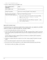
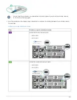
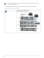
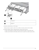
Step
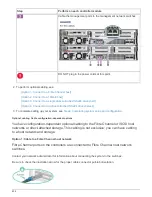
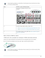
Perform on each controller module
1
Cable ports e4a through e4d to the 10GbE host network
switches.
2
To perform other optional cabling, choose from:
•
[Option 3: Connect to a single direct-attached NS224 drive shelf]
•
[Option 4: Connect to two direct-attached NS224 drive shelves]
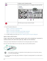
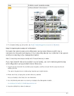
3
To complete setting up your system, see
.
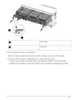
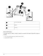
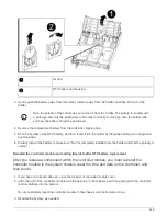
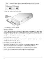
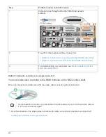
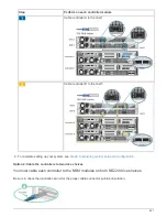
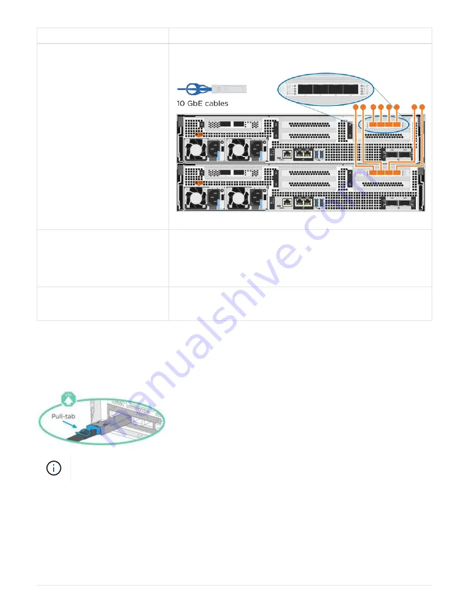
Option 3: Cable the controllers to a single drive shelf
You must cable each controller to the NSM modules on the NS224 drive shelf.
Be sure to check the illustration arrow for the proper cable connector pull-tab orientation.
As you insert the connector, you should feel it click into place; if you do not feel it click, remove
it, turn it around and try again.
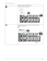
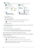
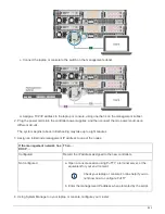
1. Use the animation or the step-by-step instructions to cable your controller modules to a single shelf.
Cabling the controllers to a single drive shelf
840
Summary of Contents for AFF A700
Page 4: ...AFF and FAS System Documentation 1...
Page 208: ...3 Close the controller module cover and tighten the thumbscrew 205...
Page 248: ...2 Close the controller module cover and tighten the thumbscrew 245...
Page 308: ...Power supply Cam handle release latch Power and Fault LEDs Cam handle 305...
Page 381: ...Power supply Cam handle release latch Power and Fault LEDs Cam handle 378...
Page 437: ...1 Locate the DIMMs on your controller module 434...
Page 605: ...602...
Page 1117: ...3 Close the controller module cover and tighten the thumbscrew 1114...
Page 1157: ...2 Close the controller module cover and tighten the thumbscrew 1154...
Page 1228: ...Power supply Cam handle release latch Power and Fault LEDs Cam handle 1225...
Page 1300: ...Power supply Cam handle release latch Power and Fault LEDs Cam handle 1297...
Page 1462: ...Installing SuperRail to round hole four post rack 1459...
Page 1602: ...1599...
Page 1630: ...1627...
Page 1634: ...Orange ring on horizontal bracket Cable chain 1631...
Page 1645: ...Guide rail 1642...
Page 1669: ...Attention LED light on 1666...