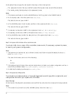
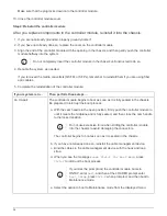

It is important that you apply the commands in the steps on the correct systems:
• The
replacement
node is the new node that replaced the impaired node as part of this procedure.
• The
healthy
node is the HA partner of the
replacement
node
Steps
1. If the
replacement
node is not at the LOADER prompt, halt the system to the LOADER prompt.
2. On the healthy node, check the system time:
show date
The date and time are given in GMT.
3. At the LOADER prompt, check the date and time on the
replacement
node:
show date
The date and time are given in GMT.
4. If necessary, set the date in GMT on the replacement node:
set date
mm/dd/yyyy
5. If necessary, set the time in GMT on the replacement node:
set time
hh:mm:ss
6. At the LOADER prompt, confirm the date and time on the
replacement
node:
show date
The date and time are given in GMT.
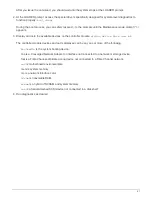
Step 2: Verify and set the HA state of the controller module
You must verify the
HA
state of the controller module and, if necessary, update the state
to match your system configuration.
Steps
1. In Maintenance mode from the new controller module, verify that all components display the same
HA
state:
ha-config show
The value for HA-state can be one of the following:
◦
ha
◦
non-ha
2. If the displayed system state of the controller module does not match your system configuration, set the
HA
state for the controller module:
ha-config modify controller ha-state
3. Confirm that the setting has changed:
ha-config show
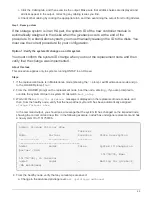
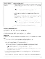
Step 3: Run system-level diagnostics
You should run comprehensive or focused diagnostic tests for specific components and
subsystems whenever you replace the controller.
About this task
All commands in the diagnostic procedures are issued from the node where the component is being replaced.
Steps
1. If the node to be serviced is not at the LOADER prompt, reboot the node:
halt
40
Summary of Contents for AFF A700
Page 4: ...AFF and FAS System Documentation 1...
Page 208: ...3 Close the controller module cover and tighten the thumbscrew 205...
Page 248: ...2 Close the controller module cover and tighten the thumbscrew 245...
Page 308: ...Power supply Cam handle release latch Power and Fault LEDs Cam handle 305...
Page 381: ...Power supply Cam handle release latch Power and Fault LEDs Cam handle 378...
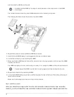
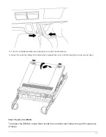
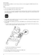
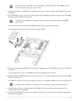
Page 437: ...1 Locate the DIMMs on your controller module 434...
Page 605: ...602...
Page 1117: ...3 Close the controller module cover and tighten the thumbscrew 1114...
Page 1157: ...2 Close the controller module cover and tighten the thumbscrew 1154...
Page 1228: ...Power supply Cam handle release latch Power and Fault LEDs Cam handle 1225...
Page 1300: ...Power supply Cam handle release latch Power and Fault LEDs Cam handle 1297...
Page 1462: ...Installing SuperRail to round hole four post rack 1459...
Page 1602: ...1599...
Page 1630: ...1627...
Page 1634: ...Orange ring on horizontal bracket Cable chain 1631...
Page 1645: ...Guide rail 1642...
Page 1669: ...Attention LED light on 1666...


