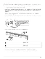

3. Recable the system, as needed.
If you removed the media converters (QSFPs or SFPs), remember to reinstall them if you are using fiber
optic cables.
4. If the power supplies were unplugged, plug them back in and reinstall the power cable retainers.
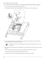
5. Insert the controller module into the chassis:
a. Ensure the latching mechanism arms are locked in the fully extended position.
b. Using both hands, align and gently slide the controller module into the latching mechanism arms until it
stops.
c. Place your index fingers through the finger holes from the inside of the latching mechanism.
d. Press your thumbs down on the orange tabs on top of the latching mechanism and gently push the
controller module over the stop.
e. Release your thumbs from the top of the latching mechanisms and continue pushing until the latching
mechanisms snap into place.
The controller module begins to boot as soon as it is fully seated in the chassis. Be prepared to
interrupt the boot process.
f. Halt the controller at the LOADER prompt.
The controller module should be fully inserted and flush with the edges of the chassis.
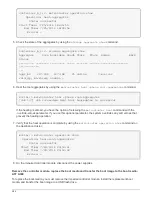
6. Reset the time and date on the controller:
a. Check the date and time on the healthy node with the
show date
command.
b. At the LOADER prompt on the target node, check the time and date.
c. If necessary, modify the date with the
set date mm/dd/yyyy
command.
d. If necessary, set the time, in GMT, using the
set time hh:mm:ss
command.
e. Confirm the date and time on the target node.
7. At the LOADER prompt, enter
bye
to reinitialize the PCIe cards and other components and let the node
reboot.
8. Return the node to normal operation by giving back its storage:
storage failover giveback
-ofnode
impaired_node_name
9. If automatic giveback was disabled, reenable it:
storage failover modify -node local -auto
-giveback true
Step 5: Return the failed part to NetApp
After you replace the part, you can return the failed part to NetApp, as described in the
RMA instructions shipped with the kit. Contact technical support at
, 888-
463-8277 (North America), 00-800-44-638277 (Europe), or +800-800-80-800
(Asia/Pacific) if you need the RMA number or additional help with the replacement
procedure.
275
Summary of Contents for AFF A700
Page 4: ...AFF and FAS System Documentation 1...
Page 208: ...3 Close the controller module cover and tighten the thumbscrew 205...
Page 248: ...2 Close the controller module cover and tighten the thumbscrew 245...
Page 308: ...Power supply Cam handle release latch Power and Fault LEDs Cam handle 305...
Page 381: ...Power supply Cam handle release latch Power and Fault LEDs Cam handle 378...
Page 437: ...1 Locate the DIMMs on your controller module 434...
Page 605: ...602...
Page 1117: ...3 Close the controller module cover and tighten the thumbscrew 1114...
Page 1157: ...2 Close the controller module cover and tighten the thumbscrew 1154...
Page 1228: ...Power supply Cam handle release latch Power and Fault LEDs Cam handle 1225...
Page 1300: ...Power supply Cam handle release latch Power and Fault LEDs Cam handle 1297...
Page 1462: ...Installing SuperRail to round hole four post rack 1459...
Page 1602: ...1599...
Page 1630: ...1627...
Page 1634: ...Orange ring on horizontal bracket Cable chain 1631...
Page 1645: ...Guide rail 1642...
Page 1669: ...Attention LED light on 1666...