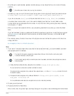

You can enter the command on either controller module.
2. Assign each drive:
storage disk assign -disk disk_name -owner owner_name
You can enter the command on either controller module.
You can use the wild card character to assign more than one drive at once.
3. Reenable automatic drive assignment if needed:
storage disk option modify -node node_name
-autoassign on
You must reenable automatic drive assignment on both controller modules.
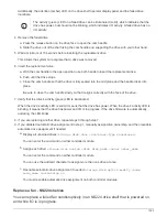
Change a shelf ID - NS224 shelves
You can change a shelf ID in a system when ONTAP is not yet running or when hot-
adding a shelf prior to it being cabled to the system. You can also change a shelf ID when
ONTAP is up and running (controller modules are available to serve data) and all drives in
the shelf are unowned, spares, or part of offlined aggregate(s).
Before you begin
• If ONTAP is up and running (controller modules are available to serve data), you must have verified that all
drives in the shelf are unowned, spares, or part of offlined aggregate(s).
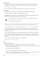
You can verify the state of the drives by using the
storage disk show -shelf
shelf_number
command. Output in the
Container Type
column should display
spare
or
broken
if it is a failed drive.
Additionally, the
Container Name
and
Owner
columns should have a dash.
• You need a paper clip with one side straightened or a narrow tipped ballpoint pen.
You use the paper clip or ballpoint pen to access the shelf ID button through the small hole, to the right of
the LEDs, in the Operator Display Panel (ODP).
About this task
• A valid shelf ID is 00 through 99.
• Shelf IDs must be unique within an HA pair.
• You must power cycle a shelf (unplug both power cords, wait the appropriate amount of time, and then plug
them back in) in order for the shelf ID to take effect.
The amount of time you wait before plugging the power cords back in depends on the state of ONTAP, as
described later in this procedure.
NS224 shelves do not have power switches on the power supplies.
Steps
1. Power on the shelf, if it’s not already on.
You connect the power cords first to the shelf, securing them in place with the power cord retainer, and
then connect the power cords to different power sources for resiliency.
1512
Summary of Contents for AFF A700
Page 4: ...AFF and FAS System Documentation 1...
Page 208: ...3 Close the controller module cover and tighten the thumbscrew 205...
Page 248: ...2 Close the controller module cover and tighten the thumbscrew 245...
Page 308: ...Power supply Cam handle release latch Power and Fault LEDs Cam handle 305...
Page 381: ...Power supply Cam handle release latch Power and Fault LEDs Cam handle 378...
Page 437: ...1 Locate the DIMMs on your controller module 434...
Page 605: ...602...
Page 1117: ...3 Close the controller module cover and tighten the thumbscrew 1114...
Page 1157: ...2 Close the controller module cover and tighten the thumbscrew 1154...
Page 1228: ...Power supply Cam handle release latch Power and Fault LEDs Cam handle 1225...
Page 1300: ...Power supply Cam handle release latch Power and Fault LEDs Cam handle 1297...
Page 1462: ...Installing SuperRail to round hole four post rack 1459...
Page 1602: ...1599...
Page 1630: ...1627...
Page 1634: ...Orange ring on horizontal bracket Cable chain 1631...
Page 1645: ...Guide rail 1642...
Page 1669: ...Attention LED light on 1666...