

If the system-level
diagnostics tests…
Then…
Resulted in some test
failures
Determine the cause of the problem:
a. Exit Maintenance mode:
halt
After you issue the command, wait until the system stops at the LOADER
prompt.
b. Turn off or leave on the power supplies, depending on how many controller
modules are in the chassis:
◦
If you have two controller modules in the chassis, leave the power
supplies turned on to provide power to the other controller module.
◦
If you have one controller module in the chassis, turn off the power
supplies and unplug them from the power sources.
c. Verify that you have observed all the considerations identified for running
system-level diagnostics, that cables are securely connected, and that
hardware components are properly installed in the storage system.
d. Boot the controller module you are servicing, interrupting the boot by
pressing
Ctrl-C
when prompted to get to the Boot menu:
◦
If you have two controller modules in the chassis, fully seat the
controller module you are servicing in the chassis.
The controller module boots up when fully seated.
◦
If you have one controller module in the chassis, connect the power
supplies, and then turn them on.
e. Select Boot to maintenance mode from the menu.
f. Exit Maintenance mode by entering the following command:
halt
After you issue the command, wait until the system stops at the LOADER
prompt.
g. Rerun the system-level diagnostic test.
Step 6: Return the failed part to NetApp
After you replace the part, you can return the failed part to NetApp, as described in the
RMA instructions shipped with the kit. Contact technical support at
, 888-
463-8277 (North America), 00-800-44-638277 (Europe), or +800-800-80-800
(Asia/Pacific) if you need the RMA number or additional help with the replacement
procedure.
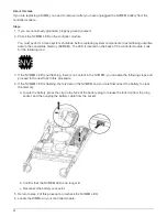
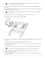
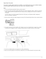
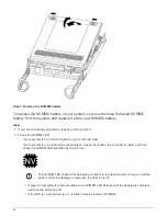
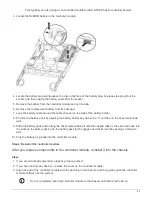
Replace the NVMEM battery - AFF A200
To replace an NVMEM battery in the system, you must remove the controller module from
the system, open it, replace the battery, and close and replace the controller module.
59
Summary of Contents for AFF A700
Page 4: ...AFF and FAS System Documentation 1...
Page 208: ...3 Close the controller module cover and tighten the thumbscrew 205...
Page 248: ...2 Close the controller module cover and tighten the thumbscrew 245...
Page 308: ...Power supply Cam handle release latch Power and Fault LEDs Cam handle 305...
Page 381: ...Power supply Cam handle release latch Power and Fault LEDs Cam handle 378...
Page 437: ...1 Locate the DIMMs on your controller module 434...
Page 605: ...602...
Page 1117: ...3 Close the controller module cover and tighten the thumbscrew 1114...
Page 1157: ...2 Close the controller module cover and tighten the thumbscrew 1154...
Page 1228: ...Power supply Cam handle release latch Power and Fault LEDs Cam handle 1225...
Page 1300: ...Power supply Cam handle release latch Power and Fault LEDs Cam handle 1297...
Page 1462: ...Installing SuperRail to round hole four post rack 1459...
Page 1602: ...1599...
Page 1630: ...1627...
Page 1634: ...Orange ring on horizontal bracket Cable chain 1631...
Page 1645: ...Guide rail 1642...
Page 1669: ...Attention LED light on 1666...


