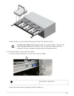
Risk of equipment malfunction:
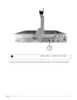
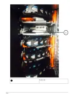
Make sure to slide the connector underneath the
guide rail on the bracket. If the connector rests on the top of the guide rail, problems
might occur when the system runs.
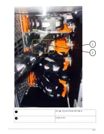
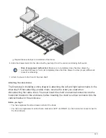
d. Slide the vertical connector on the left cable chain into the vertical bracket.
e. After you have reconnected both ends of the cable chain, carefully pull on the cable chain to verify that
both connectors are latched.
Risk of equipment malfunction:
If the connectors are not latched, the cable chain
might come loose during drawer operation.
2. Reinstall the left fan module.
3. Follow these steps to reattach the right cable chain:
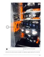
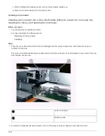
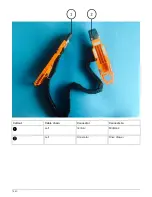
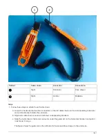
a. Locate the horizontal and vertical connectors on the cable chain and their corresponding horizontal and
vertical brackets inside the enclosure.
b. Align both cable chain connectors with their corresponding brackets.
c. Slide the cable chain’s horizontal connector under the guide rail on the horizontal bracket and push it in
as far as it will go.
Risk of equipment malfunction:
Make sure to slide the connector underneath the
guide rail on the bracket. If the connector rests on the top of the guide rail, problems
might occur when the system runs.
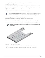
d. Slide the vertical connector on the right cable chain into the vertical bracket.
e. After you reconnect both ends of the cable chain, carefully pull on the cable chain to verify that both
connectors are latched.
Risk of equipment malfunction:
If the connectors are not latched, the cable chain
might come loose during drawer operation.
4. Reinstall the right fan module.
5. Reapply power:
a. Turn on both power switches on the drive shelf.
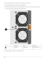
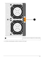
b. Confirm that both fans come on and that the amber LED on the back of the fans is off.
Replace a fan module in a DS460C disk shelf - shelves with IOM12 modules
Each DS460C drive shelf includes two fan modules. If a fan module fails, you must
replace it as soon as possible to ensure that the shelf has adequate cooling. When you
remove the failed fan module, you do not have to turn off power to your disk shelf.
About this task
You must ensure that you remove and replace the fan module within 30 minutes to prevent the system from
overheating.
Steps
1. Put on antistatic protection.
1643
Summary of Contents for AFF A700
Page 4: ...AFF and FAS System Documentation 1...
Page 208: ...3 Close the controller module cover and tighten the thumbscrew 205...
Page 248: ...2 Close the controller module cover and tighten the thumbscrew 245...
Page 308: ...Power supply Cam handle release latch Power and Fault LEDs Cam handle 305...
Page 381: ...Power supply Cam handle release latch Power and Fault LEDs Cam handle 378...
Page 437: ...1 Locate the DIMMs on your controller module 434...
Page 605: ...602...
Page 1117: ...3 Close the controller module cover and tighten the thumbscrew 1114...
Page 1157: ...2 Close the controller module cover and tighten the thumbscrew 1154...
Page 1228: ...Power supply Cam handle release latch Power and Fault LEDs Cam handle 1225...
Page 1300: ...Power supply Cam handle release latch Power and Fault LEDs Cam handle 1297...
Page 1462: ...Installing SuperRail to round hole four post rack 1459...
Page 1602: ...1599...
Page 1630: ...1627...
Page 1634: ...Orange ring on horizontal bracket Cable chain 1631...
Page 1645: ...Guide rail 1642...
Page 1669: ...Attention LED light on 1666...

