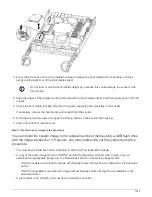
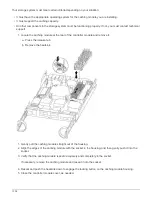
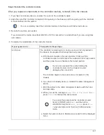
3. Press the blue button on the boot media housing to release the boot media from its housing, and then
gently pull it straight out of the boot media socket.
Do not twist or pull the boot media straight up, because this could damage the socket or the
boot media.
4. Align the edges of the replacement boot media with the boot media socket, and then gently push it into the
socket.
5. Check the boot media to make sure that it is seated squarely and completely in the socket.
If necessary, remove the boot media and reseat it into the socket.
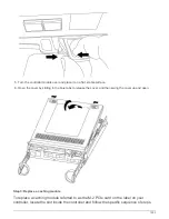
6. Push the boot media down to engage the locking button on the boot media housing.
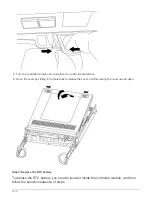
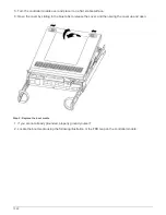
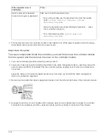
7. Close the controller module cover.
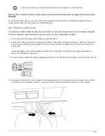
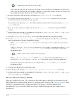
Step 3: Transfer the boot image to the boot media
You can install the system image to the replacement boot media using a USB flash drive
with the image installed on it. However, you must restore the var file system during this
procedure.
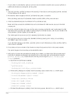
• You must have a USB flash drive, formatted to FAT32, with at least 4GB capacity.
• A copy of the same image version of ONTAP as what the impaired controller was running. You can
download the appropriate image from the Downloads section on the NetApp Support Site
◦
If NVE is enabled, download the image with NetApp Volume Encryption, as indicated in the download
button.
◦
If NVE is not enabled, download the image without NetApp Volume Encryption, as indicated in the
download button.
• If your system is an HA pair, you must have a network connection.
1023
Summary of Contents for AFF A700
Page 4: ...AFF and FAS System Documentation 1...
Page 208: ...3 Close the controller module cover and tighten the thumbscrew 205...
Page 248: ...2 Close the controller module cover and tighten the thumbscrew 245...
Page 308: ...Power supply Cam handle release latch Power and Fault LEDs Cam handle 305...
Page 381: ...Power supply Cam handle release latch Power and Fault LEDs Cam handle 378...
Page 437: ...1 Locate the DIMMs on your controller module 434...
Page 605: ...602...
Page 1117: ...3 Close the controller module cover and tighten the thumbscrew 1114...
Page 1157: ...2 Close the controller module cover and tighten the thumbscrew 1154...
Page 1228: ...Power supply Cam handle release latch Power and Fault LEDs Cam handle 1225...
Page 1300: ...Power supply Cam handle release latch Power and Fault LEDs Cam handle 1297...
Page 1462: ...Installing SuperRail to round hole four post rack 1459...
Page 1602: ...1599...
Page 1630: ...1627...
Page 1634: ...Orange ring on horizontal bracket Cable chain 1631...
Page 1645: ...Guide rail 1642...
Page 1669: ...Attention LED light on 1666...


