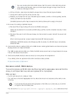
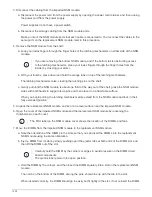
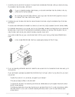
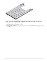
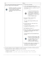
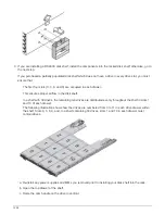

d. Loop your index fingers through the finger holes of the latching mechanisms on either side of the NSM
module.
If you are inserting the bottom NSM module, and if the bottom rail is obstructing access
to the latching mechanisms, place your index fingers through the finger holes from the
inside (by crossing your arms).
e. With your thumbs, press down and hold the orange tabs on top of the latching mechanisms.
f. Gently push forward to get the latches over the stop.
g. Release your thumbs from the tops of the latching mechanisms, and then continue pushing until the
latching mechanisms snap into place.
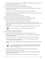
The NSM module should be fully inserted into the shelf and flush with the edges of the shelf.
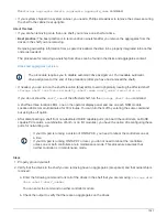
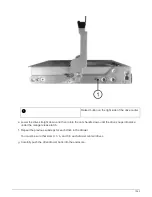
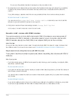
9. Reconnect the cabling to the NSM module:
a. Reconnect the storage cabling to the same two NSM module ports.
Cables are inserted with the connector pull-tab facing up. When a cable is inserted correctly, it clicks
into place.
b. Reconnect the power cord to the power supply, and then secure the power cord with the power cord
retainer.
When functioning correctly, a power supply’s bicolored LED illuminates green.
Additionally, both NSM module port LNK (green) LEDs illuminate. If a LNK LED does not illuminate,
reseat the cable.
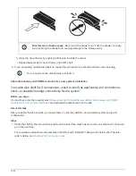
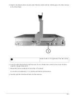
10. Verify that the attention (amber) LEDs on the NSM module containing the failed RTC battery and the shelf
operator display panel are no longer illuminated
The NSM module attention LEDs turn off after the NSM module reboots and no longer detects an RTC
battery issue. This can take three to five minutes.
11. Verify that the NSM module is cabled correctly, by running Active IQ Config Advisor.
If any cabling errors are generated, follow the corrective actions provided.
NetApp Downloads: Config Advisor
1538
Summary of Contents for AFF A700
Page 4: ...AFF and FAS System Documentation 1...
Page 208: ...3 Close the controller module cover and tighten the thumbscrew 205...
Page 248: ...2 Close the controller module cover and tighten the thumbscrew 245...
Page 308: ...Power supply Cam handle release latch Power and Fault LEDs Cam handle 305...
Page 381: ...Power supply Cam handle release latch Power and Fault LEDs Cam handle 378...
Page 437: ...1 Locate the DIMMs on your controller module 434...
Page 605: ...602...
Page 1117: ...3 Close the controller module cover and tighten the thumbscrew 1114...
Page 1157: ...2 Close the controller module cover and tighten the thumbscrew 1154...
Page 1228: ...Power supply Cam handle release latch Power and Fault LEDs Cam handle 1225...
Page 1300: ...Power supply Cam handle release latch Power and Fault LEDs Cam handle 1297...
Page 1462: ...Installing SuperRail to round hole four post rack 1459...
Page 1602: ...1599...
Page 1630: ...1627...
Page 1634: ...Orange ring on horizontal bracket Cable chain 1631...
Page 1645: ...Guide rail 1642...
Page 1669: ...Attention LED light on 1666...