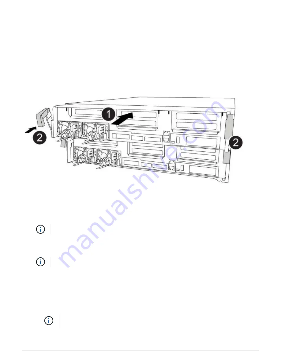
Step 4: Install the controller module
After you have replaced the component in the controller module, you must re-install the
controller module into the chassis, and then boot it to Maintenance mode.
You can use the following animation, illustration, or the written steps to install the controller module in the
chassis.
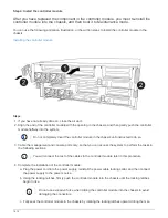
Installing the controller module
Steps
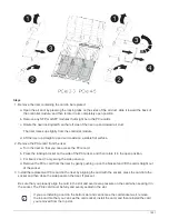
1. If you have not already done so, close the air duct.
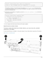
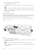
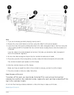
2. Align the end of the controller module with the opening in the chassis, and then gently push the controller
module halfway into the system.
Do not completely insert the controller module in the chassis until instructed to do so.
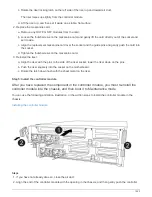
3. Cable the management and console ports only, so that you can access the system to perform the tasks in
the following sections.
You will connect the rest of the cables to the controller module later in this procedure.
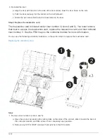
4. Complete the installation of the controller module:
a. Plug the power cord into the power supply, reinstall the power cable locking collar, and then connect
the power supply to the power source.
b. Using the locking latches, firmly push the controller module into the chassis until the locking latches
begin to rise.
Do not use excessive force when sliding the controller module into the chassis to avoid
damaging the connectors.
c. Fully seat the controller module in the chassis by rotating the locking latches upward, tilting them so
1412
Summary of Contents for AFF A700
Page 4: ...AFF and FAS System Documentation 1...
Page 208: ...3 Close the controller module cover and tighten the thumbscrew 205...
Page 248: ...2 Close the controller module cover and tighten the thumbscrew 245...
Page 308: ...Power supply Cam handle release latch Power and Fault LEDs Cam handle 305...
Page 381: ...Power supply Cam handle release latch Power and Fault LEDs Cam handle 378...
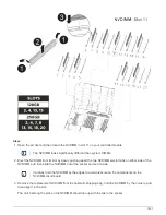
Page 437: ...1 Locate the DIMMs on your controller module 434...
Page 605: ...602...
Page 1117: ...3 Close the controller module cover and tighten the thumbscrew 1114...
Page 1157: ...2 Close the controller module cover and tighten the thumbscrew 1154...
Page 1228: ...Power supply Cam handle release latch Power and Fault LEDs Cam handle 1225...
Page 1300: ...Power supply Cam handle release latch Power and Fault LEDs Cam handle 1297...
Page 1462: ...Installing SuperRail to round hole four post rack 1459...
Page 1602: ...1599...
Page 1630: ...1627...
Page 1634: ...Orange ring on horizontal bracket Cable chain 1631...
Page 1645: ...Guide rail 1642...
Page 1669: ...Attention LED light on 1666...