power supply and installing, connecting, and turning on the replacement power supply.
All other components in the system must be functioning properly; if not, you must contact technical support.
• The power supplies are redundant and hot-swappable.
• This procedure is written for replacing one power supply at a time.
Cooling is integrated with the power supply, so you must replace the power supply within
two minutes of removal to prevent overheating due to reduced airflow. Because the chassis
provides a shared cooling configuration for the two HA nodes, a delay longer than two
minutes will shut down all controller modules in the chassis. If both controller modules do
shut down, make sure that both power supplies are inserted, turn both off for 30 seconds,
and then turn both on.
• The number of power supplies in the system depends on the model.
• Power supplies are auto-ranging.
AFF FAS2600 power supply replacement video
1. Identify the power supply you want to replace, based on console error messages or through the LEDs on
the power supplies.
2. If you are not already grounded, properly ground yourself.
3. Turn off the power supply and disconnect the power cables:
a. Turn off the power switch on the power supply.
b. Open the power cable retainer, and then unplug the power cable from the power supply.
c. Unplug the power cable from the power source.
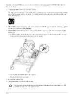
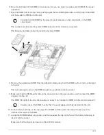
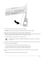
4. Squeeze the latch on the power supply cam handle, and then open the cam handle to fully release the
power supply from the mid plane.
1086
Summary of Contents for AFF A700
Page 4: ...AFF and FAS System Documentation 1...
Page 208: ...3 Close the controller module cover and tighten the thumbscrew 205...
Page 248: ...2 Close the controller module cover and tighten the thumbscrew 245...
Page 308: ...Power supply Cam handle release latch Power and Fault LEDs Cam handle 305...
Page 381: ...Power supply Cam handle release latch Power and Fault LEDs Cam handle 378...
Page 437: ...1 Locate the DIMMs on your controller module 434...
Page 605: ...602...
Page 1117: ...3 Close the controller module cover and tighten the thumbscrew 1114...
Page 1157: ...2 Close the controller module cover and tighten the thumbscrew 1154...
Page 1228: ...Power supply Cam handle release latch Power and Fault LEDs Cam handle 1225...
Page 1300: ...Power supply Cam handle release latch Power and Fault LEDs Cam handle 1297...
Page 1462: ...Installing SuperRail to round hole four post rack 1459...
Page 1602: ...1599...
Page 1630: ...1627...
Page 1634: ...Orange ring on horizontal bracket Cable chain 1631...
Page 1645: ...Guide rail 1642...
Page 1669: ...Attention LED light on 1666...

