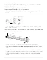
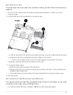

c. Press down and hold the orange tabs on top of the latching mechanism.
d. Gently push the controller module into the chassis bay until it is flush with the edges of the chassis.
The latching mechanism arms slide into the chassis.
The controller module begins to boot as soon as it is fully seated in the chassis.
e. Release the latches to lock the controller module into place.
f. If you have not already done so, reinstall the cable management device.
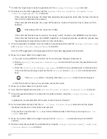
8. Interrupt the boot process by pressing Ctrl-C to stop at the LOADER prompt.
If you miss this message, press Ctrl-C, select the option to boot to Maintenance mode, and then halt
the node to boot to LOADER.
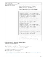
9. Although the environment variables and bootargs are retained, you should check that all required boot
environment variables and bootargs are properly set for your system type and configuration using the
printenv bootarg name
command and correct any errors using the
setenv variable-name
<value>
command.
a. Check the boot environment variables:
▪
bootarg.init.boot_clustered
▪
partner-sysid
▪
bootarg.init.flash_optimized
for AFF C190/AFF A220 (All Flash FAS)
▪
bootarg.init.san_optimized
for AFF A220 and All SAN Array
▪
bootarg.init.switchless_cluster.enable
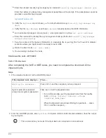
b. If External Key Manager is enabled, check the bootarg values, listed in the
kenv
ASUP output:
▪
bootarg.storageencryption.support <value>
▪
bootarg.keymanager.support <value>
▪
kmip.init.interface <value>
▪
kmip.init.ipaddr <value>
▪
kmip.init.netmask <value>
▪
kmip.init.gateway <value>
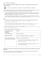
c. If Onboard Key Manager is enabled, check the bootarg values, listed in the
kenv
ASUP output:
▪
bootarg.storageencryption.support <value>
▪
bootarg.keymanager.support <value>
▪
bootarg.onboard_keymanager <value>
d. Save the environment variables you changed with the
savenv
command
e. Confirm your changes using the
printenv
variable-name
command.
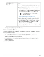
10. From the LOADER prompt, boot the recovery image from the USB flash drive:
boot_recovery
The image is downloaded from the USB flash drive.
413
Summary of Contents for AFF A700
Page 4: ...AFF and FAS System Documentation 1...
Page 208: ...3 Close the controller module cover and tighten the thumbscrew 205...
Page 248: ...2 Close the controller module cover and tighten the thumbscrew 245...
Page 308: ...Power supply Cam handle release latch Power and Fault LEDs Cam handle 305...
Page 381: ...Power supply Cam handle release latch Power and Fault LEDs Cam handle 378...
Page 437: ...1 Locate the DIMMs on your controller module 434...
Page 605: ...602...
Page 1117: ...3 Close the controller module cover and tighten the thumbscrew 1114...
Page 1157: ...2 Close the controller module cover and tighten the thumbscrew 1154...
Page 1228: ...Power supply Cam handle release latch Power and Fault LEDs Cam handle 1225...
Page 1300: ...Power supply Cam handle release latch Power and Fault LEDs Cam handle 1297...
Page 1462: ...Installing SuperRail to round hole four post rack 1459...
Page 1602: ...1599...
Page 1630: ...1627...
Page 1634: ...Orange ring on horizontal bracket Cable chain 1631...
Page 1645: ...Guide rail 1642...
Page 1669: ...Attention LED light on 1666...