

Steps
1. If the node to be serviced is not at the LOADER prompt, reboot the node:
system node halt -node
node_name
After you issue the command, you should wait until the system stops at the LOADER prompt.
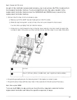
2. At the LOADER prompt, access the special drivers specifically designed for system-level diagnostics to
function properly:
boot_diags
3. Select
Scan System
from the displayed menu to enable running the diagnostics tests.
4. Select
Test Memory
from the displayed menu.
5. Proceed based on the result of the preceding step:
◦
If the test failed, correct the failure, and then rerun the test.
◦
If the test reported no failures, select Reboot from the menu to reboot the system.
Step 3: Return the failed part to NetApp
After you replace the part, you can return the failed part to NetApp, as described in the
RMA instructions shipped with the kit. Contact technical support at
, 888-
463-8277 (North America), 00-800-44-638277 (Europe), or +800-800-80-800
(Asia/Pacific) if you need the RMA number or additional help with the replacement
procedure.
Controller
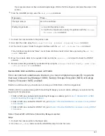
Replace the controller module - AFF A800
You must review the prerequisites for the replacement procedure and select the correct
one for your version of the ONTAP operating system.
• All drive shelves must be working properly.
• The healthy node must be able to take over the node that is being replaced (referred to in this procedure
as the “impaired node”).
• If your system is in a MetroCluster configuration, you must review the section
to determine whether you should use this procedure.
• You must replace the failed component with a replacement FRU component you received from your
provider.
• You must be replacing a controller module with a controller module of the same model type. You cannot
upgrade your system by just replacing the controller module.
• You cannot change any drives or drive shelves as part of this procedure.
• In this procedure, the boot device is moved from the impaired node to the
replacement
node so that the
replacement
node will boot up in the same version of ONTAP as the old controller module.
• It is important that you apply the commands in these steps on the correct systems:
◦
The
impaired
node is the node that is being replaced.
◦
The
replacement node
is the new node that is replacing the impaired node.
◦
The
healthy node
is the surviving node.
874
Summary of Contents for AFF A700
Page 4: ...AFF and FAS System Documentation 1...
Page 208: ...3 Close the controller module cover and tighten the thumbscrew 205...
Page 248: ...2 Close the controller module cover and tighten the thumbscrew 245...
Page 308: ...Power supply Cam handle release latch Power and Fault LEDs Cam handle 305...
Page 381: ...Power supply Cam handle release latch Power and Fault LEDs Cam handle 378...
Page 437: ...1 Locate the DIMMs on your controller module 434...
Page 605: ...602...
Page 1117: ...3 Close the controller module cover and tighten the thumbscrew 1114...
Page 1157: ...2 Close the controller module cover and tighten the thumbscrew 1154...
Page 1228: ...Power supply Cam handle release latch Power and Fault LEDs Cam handle 1225...
Page 1300: ...Power supply Cam handle release latch Power and Fault LEDs Cam handle 1297...
Page 1462: ...Installing SuperRail to round hole four post rack 1459...
Page 1602: ...1599...
Page 1630: ...1627...
Page 1634: ...Orange ring on horizontal bracket Cable chain 1631...
Page 1645: ...Guide rail 1642...
Page 1669: ...Attention LED light on 1666...


