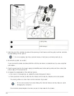


e. Select the option to boot to Maintenance mode from the displayed menu.
Verify the system ID change on an HA system
You must confirm the system ID change when you boot the
replacement
node and then
verify that the change was implemented.
This procedure applies only to systems running ONTAP in an HA pair.
1. If the
replacement
node is in Maintenance mode (showing the
*>
prompt, exit Maintenance mode and go
to the LOADER prompt:
halt
2. From the LOADER prompt on the
replacement
node, boot the node, entering
y
if you are prompted to
override the system ID due to a system ID mismatch:
boot_ontap
3. Wait until the
Waiting for giveback…
message is displayed on the
replacement
node console and
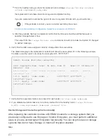
then, from the healthy node, verify that the new partner system ID has been automatically assigned:
storage failover show
In the command output, you should see a message that the system ID has changed on the impaired node,
showing the correct old and new IDs. In the following example, node2 has undergone replacement and has
a new system ID of 151759706.
node1> storage failover show
Takeover
Node Partner Possible State Description
------------ ------------ --------
-------------------------------------
node1 node2 false System ID changed on
partner (Old:
151759755, New:
151759706), In takeover
node2 node1 - Waiting for giveback
(HA mailboxes)
4. From the healthy node, verify that any coredumps are saved:
a. Change to the advanced privilege level:
set -privilege advanced
You can respond
Y
when prompted to continue into advanced mode. The advanced mode prompt
appears (*>).
b. Save any coredumps:
system node run -node
local-node-name
partner savecore
c. Wait for savecore command to complete before issuing the giveback.
You can enter the following command to monitor the progress of the savecore command:
system
node run -node
local-node-name
partner savecore -s
d. Return to the admin privilege level:
set -privilege admin
5. Give back the node:
815
Summary of Contents for AFF A700
Page 4: ...AFF and FAS System Documentation 1...
Page 208: ...3 Close the controller module cover and tighten the thumbscrew 205...
Page 248: ...2 Close the controller module cover and tighten the thumbscrew 245...
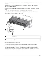
Page 308: ...Power supply Cam handle release latch Power and Fault LEDs Cam handle 305...
Page 381: ...Power supply Cam handle release latch Power and Fault LEDs Cam handle 378...
Page 437: ...1 Locate the DIMMs on your controller module 434...
Page 605: ...602...
Page 1117: ...3 Close the controller module cover and tighten the thumbscrew 1114...
Page 1157: ...2 Close the controller module cover and tighten the thumbscrew 1154...
Page 1228: ...Power supply Cam handle release latch Power and Fault LEDs Cam handle 1225...
Page 1300: ...Power supply Cam handle release latch Power and Fault LEDs Cam handle 1297...
Page 1462: ...Installing SuperRail to round hole four post rack 1459...
Page 1602: ...1599...
Page 1630: ...1627...
Page 1634: ...Orange ring on horizontal bracket Cable chain 1631...
Page 1645: ...Guide rail 1642...
Page 1669: ...Attention LED light on 1666...