Molecular Devices ImageXpress Confocal HT.ai User Manual Download Page 158

ImageXpress Confocal HT.ai High-Content Imaging System User Guide

158

5084773 A

Cleaning the Water Reservoir

Clean the water reservoir as needed when you see dirt or mold in the reservoir.

Requirements:

Phillips screwdriver
70% ethanol
250 mL (8.4 oz) deionized water, preferably sterilized

To clean the water reservoir:

1. In the MetaXpress software, do one of the following to open the instrument top door:

From the simplified menu, click Screening > Acquisition Setup > Eject Plate.
From the standard menu, click Screening > Plate Acquisition Setup > Eject Plate.

2. Exit the MetaXpress software, and power off the instrument and the external light source.

See

Shutting Down the System on page 34

.

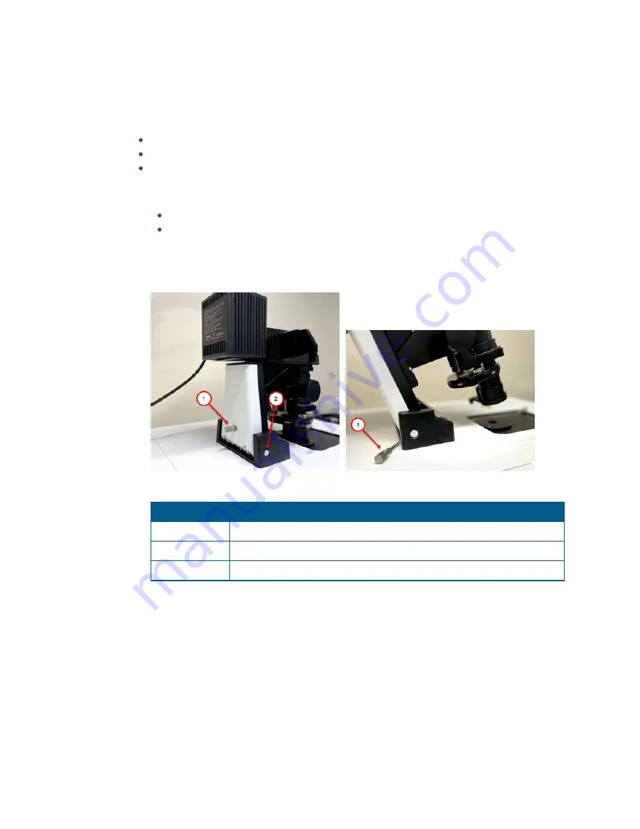
3. If your instrument includes the Transmitted Light option, remove the hinge release knob

and tilt back the Transmitted Light tower.

Figure 7-30: Hinge Release Knob and Hinge

Item

Description

1

Hinge Release Knob (in place)

2

Hinge

3

Hinge Release Knob (removed)

Table 7-6: Hinge Release Knob and Hinge Description

Summary of Contents for ImageXpress Confocal HT.ai

Page 1: ...5084773 A March 2021 ImageXpress Confocal HT ai High Content Imaging System User Guide...

Page 2: ...any right and or license to use or permit others to use such manufacturers and or their product names as trademarks Each product is shipped with documentation stating specifications and other technic...

Page 3: ...ess Confocal HT ai System 27 Starting the System 27 Understanding Status Lights 33 Maintaining the Instrument 34 Shutting Down the System 34 Chapter 3 System Installation and Testing 35 Verifying Devi...

Page 4: ...igure Tab Display Tab 121 Viewing the Summary Panel 123 Saving Plate Acquisition Protocols 124 Running Plate Acquisition Protocols 125 Chapter 6 Customizing the MetaXpress Software 127 Users and Group...

Page 5: ...pendix C Filter Specifications and Calibration Compatibility 247 Appendix D Optional Parts and Accessories 249 Appendix E File Privileges for the MetaXpress Software 251 Appendix F Robotic Plate Handl...

Page 6: ...ImageXpress Confocal HT ai High Content Imaging System User Guide 6 5084773 A...

Page 7: ...specific hazards such as biohazard electrical or laser safety warnings When danger warning or caution statements appear in this guide be careful to follow the specific safety information related to th...

Page 8: ...nts Symbol Indication Indicates that the product documentation must be consulted Indicates a potential laser hazard The instrument is rated a Class 4 high power laser product See Laser Safety on page...

Page 9: ...re to laser light hot surfaces moving parts or high voltage Safety Interlock Failure If the focusing laser stays on when the top door of the instrument is open it is unsafe to continue using the instr...

Page 10: ...h power laser products Installation and service is to be performed by a Molecular Devices Field Service Engineer only The Class 4 laser product is designed and tested in accordance with IEC 61010 1 CA...

Page 11: ...rnal light source and microscope objective and then looking into the Class 4 or Class 3b laser beam can cause severe eye injury and blindness Operate the instrument only when all the doors and panels...

Page 12: ...te the power switch on the front of the ImageXpress Systems Power and Options Controller WARNING HIGH VOLTAGE Do not operate the external light source with the external light source housing open Never...

Page 13: ...instrument unless specifically instructed to do so The moving parts inside the instrument can cause injury Do not operate the instrument with any covers or panels removed Note Observe all warnings and...

Page 14: ...ble solvents in or near an instrument that is powered on Observe the applicable cautionary procedures as defined by your safety officer when using toxic pathological or radioactive materials WARNING N...

Page 15: ...ics The water immersion controller is not watertight Water will not be contained within the controller if water spills into the water immersion controller Do not move the water immersion controller to...

Page 16: ...ImageXpress Confocal HT ai High Content Imaging System User Guide 16 5084773 A...

Page 17: ...ammable device ideally suited for user defined high speed automated assays Key components of the instrument include the following External solid state laser light source with seven channels connected...

Page 18: ...placeable parts in the solid state light source DANGER See Laser Safety on page 10 for details on the Class 4 high power laser product and specific warning and danger statements for working with the e...

Page 19: ...nd down when you change the position Sample X Y Stage Sample The plate holder is designed to scan multi well microplates in standard ANSI SBS formats with plastic or glass bottoms It can accommodate o...

Page 20: ...ives see Compatible Objectives on page 243 Disk Part Number Use 5039730 Confocal Single Disk Unit standard For basic imaging 5039731 Confocal Screening Dual Disk Unit optional For basic and high throu...

Page 21: ...location of features 1 Click Help Menu Map to display the Menu Map dialog 2 Select the Default to Customized Menu option to display the standard menu layout in the Menu Map dialog 3 Click the menu pat...

Page 22: ...gure 1 2 ImageXpress Confocal HT ai System Optical Path The ImageXpress Confocal HT ai system uses the following components and functions Fluorescence Imaging see page 23 Confocal Imaging see page 23...

Page 23: ...ntage of confocal imaging is the rejection of photons from out of focus portions of the sample and the resulting improved resolution and reduced background By changing the size of the pinhole in front...

Page 24: ...emission filter preventing it from entering the imaging system of tube lens and camera The optics in a filter cube are interference filters made by depositing thin film coatings on a glass support The...

Page 25: ...cal thickness of the plate bottom or through optimization of image quality Objectives are classified according to optical correction flatness of field numerical aperture and working distance Before yo...

Page 26: ...ImageXpress Confocal HT ai High Content Imaging System User Guide 26 5084773 A...

Page 27: ...owering On the Instrument First power on the instrument To power on the instrument 1 Confirm that the power cords for the instrument and the external light source are connected to the ImageXpress Syst...

Page 28: ...l laser light source Note See www 89north com fluorescence microscopy products by brand 89 north ldi laser diode illuminator for complete details on the external light source Figure 2 1 External Light...

Page 29: ...All instrument doors are closed The Transmitted Light tower is on and the shroud is closed 4 Confirm that the following external light source interlocks are closed The light guide interconnect box is...

Page 30: ...turns red as the instrument top door opens and closes 11 When the software completes initialization and is ready the status indicator turns green Figure 2 3 External Light Source Enabled Indicator Gr...

Page 31: ...the following a Double click the MetaXpress icon on the computer desktop b Click Start MetaXpress 6 MetaXpress 2 If the software is configured to run in multi user mode click the User Name drop down...

Page 32: ...In the Login Name field enter the login for the data source 5 In the Password field enter the password for the data source 6 Click OK 7 In the MetaXpress dialog click the Group drop down and select a...

Page 33: ...on the external light source provides information on the light source status Color External Light Source Status Yellow The light source is powered on but not ready for operation Red The light source...

Page 34: ...189 and Obtaining Support on page 237 CAUTION You must contact Molecular Devices Technical Support to schedule a Field Service Engineer to install or remove a water immersion objective Shutting Down t...

Page 35: ...tion computer ships with the MetaXpress software already installed The instrument connects to the acquisition computer during installation There are four main connections excluding power cords Fiber o...

Page 36: ...e Molecular Devices Knowledge Base at support moleculardevices com Verifying Device Settings in the Meta Imaging Series Administrator Software Use the Meta Imaging Series Administrator Software to con...

Page 37: ...ist of Groups list select MetaXpress Figure 3 2 Meta Imaging Series Administrator Software Home Dialog 4 Click Configure Hardware to display the Configure Hardware dialog 5 Click Configure Devices to...

Page 38: ...cro X Settings Dialog 7 In the Move field increase the step size to 10 000 m 8 Clear the Reverse Coordinate System check box 9 Click and and confirm that the stage responds to the control Note To see...

Page 39: ...Figure 3 6 ImageXpress Micro Y Settings Dialog 12 In the Move field increase the step size to 10 000 m 13 Select the Reverse Coordinate System check box 14 Click and and confirm that the stage respond...

Page 40: ...o Origin 21 In the Move field change the step size back to 10 m and click OK to display the User Settings dialog 22 In the Claimed Devices list select ImageXpress Micro Objective and then click Settin...

Page 41: ...camera driver 1 Click Start MetaXpress 6 Meta Imaging Series Administrator to display the Meta Imaging Series Administrator 2 Click Configure Hardware to display the Configure Hardware dialog 3 Click...

Page 42: ...lost Tip Press F1 in the MetaXpress software to view the software application help Verifying Magnification Settings Use the Configure Magnification dialog to confirm magnification settings for the Ima...

Page 43: ...efined Settings list ensure that the correct illuminations display Figure 3 12 Configure Illumination Dialog 3 Ensure that Active is selected for the appropriate shutter for each filter set CAUTION Ne...

Page 44: ...settings 1 In the MetaXpress software do one of the following to display the Calibrate Distances dialog From the simplified menu click Measure Distances Calibrate Distances From the standard menu clic...

Page 45: ...Technical Support See Obtaining Support on page 237 Objective Magnification Unbinned Pixel Size um Width mm Height mm Area mm2 1x 6 8313 13 9905 13 9905 195 7342 2x 3 4157 6 9953 6 9953 48 9335 4x 1 7...

Page 46: ...on tab 4 Select the Enable Laser Based Focusing check box 5 Select the Objective and Camera tab 6 Click the Magnification drop down and select 10x 7 Select the Plate tab 8 Click the Plate Name drop do...

Page 47: ...ease the value and click Preview Pass again If the Preview Pass image window still does not show a peak click Laser Autofocus Wizard and then follow the instructions or use the software application he...

Page 48: ...jective max 10x 5 In the Camera Binning field enter 1 6 Click the Acquisition Mode drop down and select Widefield 7 Select the Plate tab 8 Click the Plate Name drop down and select 96 Wells 8x12 9 Sel...

Page 49: ...ate materials to smolder or burn If live mode exposure is longer than 30 seconds the software automatically closes the laser shutter 22 If you use a 4x objective click the Z control arrows to step the...

Page 50: ...te type files from the MetaXpress Software Suite flash drive To load the preconfigured plate type files 1 Insert the MetaXpress Software Suite flash drive into the computer 2 When the MetaXpress softw...

Page 51: ...lick Screening Plate Acquisition Setup 3 Click Eject Plate 4 Place the test plate in position and then click Load Plate 5 Select the Configure tab 6 On the Configure tab select the Plates tab 7 Click...

Page 52: ...quisition Setup dialog From the simplified menu click Screening Acquisition Setup From the standard menu click Screening Plate Acquisition Setup 2 Select the Configure tab 3 On the Configure tab selec...

Page 53: ...cal high content and high throughput assays include one or more fluorochromes such as fluorescent proteins antibody based stains and chemical based stains You should include a nuclear stain such as Ho...

Page 54: ...s Confocal HT ai system to image whole organisms such as nematodes or zebrafish Treat the organisms with anesthetic use a gel preparation or both to immobilize the organisms for best results Homogeneo...

Page 55: ...laser light source which can cause materials to smolder or burn especially at close range Dark materials which absorb heat and materials such as plastic paper and fabric can easily be burned by visib...

Page 56: ...reproducibility of a plate allows you to set tighter focus ranges specifically for that plate type This reduces the amount of focusing needed and speeds up acquisition The major component in plate fl...

Page 57: ...sure that the buffer or media in which the cells are left is free of fluorescent components such as Phenol Red This is most important for widefield assays Several manufacturers offer media that is opt...

Page 58: ...objectives above 40x Other considerations include the numerical aperture NA of the objective the working distance and the optical corrections built into the objective With the magnification constant b...

Page 59: ...retain image resolution while increasing the image area of coverage Unless you use a journal to change settings during the experiment the sites you select are used during the entire experiment Sites c...

Page 60: ...from the background If the S N is large for example 10 then there is high confidence that the software can distinguish foreground pixels from background pixels in the image If the S N is relatively s...

Page 61: ...objects high in the sample will block the light to planes below it Instrument Maintenance For best performance your ImageXpress Confocal HT ai system should have regular preventive maintenance service...

Page 62: ...ImageXpress Confocal HT ai High Content Imaging System User Guide 62 5084773 A...

Page 63: ...plates The following sections explain the Plate Acquisition Setup dialog where you configure and run screening experiments Accessing the Plate Acquisition Setup Dialog see page 64 Plate Acquisition Se...

Page 64: ...s software displays menus along the top of the screen The Screening menu provides access to the dialogs that allow you to configure protocols and acquire images The Screening menu also provides access...

Page 65: ...e Acquisition Setup Dialog The Plate Acquisition Setup dialog provides three primary functions Use the Plate Map and Site Map area to view the plate layout and control some of the movable physical com...

Page 66: ...top door and the plate clamp so that the instrument can acquire the plate Use the Configure link to select the Sites to Visit tab below to assist with site selection When you open the Plate Acquisitio...

Page 67: ...Use the Active Wavelength drop down to select an acquisition wavelength Use the Snap icon to acquire an image without performing or re performing an autofocus Use the Start Live icon to start and sto...

Page 68: ...on Setup Dialog Configure Tab Acquisition Tab see page 90 Plate Acquisition Setup Dialog Configure Tab Display Tab see page 121 Save Protocol displays the Save Acquisition Protocol dialog where you sa...

Page 69: ...e Tab Objective and Camera Tab Use the Objective and Camera tab to set the objective magnification the camera binning and the acquisition mode for a protocol Use these settings to improve either the i...

Page 70: ...four pixels in a square a binning value of 3 combines 3x3 or nine pixels in a square and so on This reduces the image file size and resolution and increases signal to noise ratio Note If sufficient l...

Page 71: ...late before using the air objective CAUTION If you do not dry the plate bottom you run the risk of getting water on the air objective and potentially into the instrument 3 In the Camera Binning field...

Page 72: ...m Define accurate plate dimensions to prevent the instrument from making potentially hazardous movements The plate dimensions you define also ensure that laser based autofocus is as accurate as possib...

Page 73: ...pe of the well either Circle or Square Well Bottom Indicates the shape of the well bottom either Flat or Round Plate Bottom Indicates the shape of the plate bottom either Continuous or Segmented Conti...

Page 74: ...m Note The correct Plate Height value is required for autofocusing Edit Plate Bottom Settings Displays the Configure Plate Bottom Settings dialog where you adjust plate bottom settings CAUTION This di...

Page 75: ...fractive index of the material of which it is composed Although plate manufacturers generally provide reliable plate and well dimensions you must calculate the plate bottom measurements such as averag...

Page 76: ...e 6 Complete the remaining configuration fields as required See Table 5 2 Plate Settings on page 73 CAUTION You must enter the Well Depth and Plate Height values and all other plate dimensions correct...

Page 77: ...ed on the configuration options you select and the values you specify for the options Note Use the plate map and site map at the top of the Plate Acquisition Setup dialog to select and move to the wel...

Page 78: ...ray rectangle To exclude a single well click on a green well The well turns gray and the acquisition will skip the well To include the well click the well again The well turns green To exclude a colum...

Page 79: ...ecify a percentage of the field of view for the camera to acquire and then enter the X width value and Y height value This is useful to acquire images from an unevenly illuminated full field or to acq...

Page 80: ...green To exclude a contiguous group of wells drag the red outline across a group of wells The wells turn gray To include the wells drag the red outline across the group of wells again The wells turn...

Page 81: ...en sites Click Fit Sites to Well to automatically adjust the spacing between the adjacent sites to the maximum allowed value based on the plate type Click Overlap Sites 10 to automatically overlap the...

Page 82: ...it tab 2 Select the Adaptive Acquisition Site Option 3 Select the Custom Field of View check box to specify a percentage of the field of view for the camera to acquire and then enter the X width value...

Page 83: ...drag the red outline across the group of wells again The wells turn green To exclude or include all wells in the entire plate click the white triangle in the upper left corner of the plate map Note Y...

Page 84: ...s these values and the amount of overlapping you can specify Click Tile Sites to automatically adjust the spacing between adjacent sites so that there is zero spacing between sites Click Fit Sites to...

Page 85: ...ered as noise The algorithm might split larger objects that are above the maximum width into smaller objects which can affect the cell count Intensity Above Local Background Gray Levels The intensity...

Page 86: ...e selected well and site To ensure that your cell count settings are accurate bring the sample into focus before you click Test Segmentation c Click Test Segmentation to snap an image and count the nu...

Page 87: ...ftware to detect 6 Position the cursor on the dimmest part of the object and make note of the gray level value that displays in the status bar Figure 5 13 Status Bar Gray Level Indicators 7 Position t...

Page 88: ...r of wells in which a site can be simultaneously acquired This value depends on the plate well density and the magnification that you configure for the protocol Common configurations for multi well ac...

Page 89: ...ick on the number header The column of wells turns gray and the acquisition will skip the well To include the column click the column header again The wells turn green To exclude a row of wells click...

Page 90: ...the protocol Most acquisition options you select add an additional tab to the Configure tab Figure 5 15 Acquisition Tab on the Configure Tab See the following sections Configuring Autofocus Options on...

Page 91: ...f focus debris is in a sample You can configure one or both autofocus options for a plate acquisition protocol Except for oil immersion objectives we recommend primarily using Laser Based Focusing For...

Page 92: ...ing Focus on Well Bottom The recommended option for most plate acquisition protocols The initial focus on the plate for finding the samples focuses on both the plate bottom and well bottom As the syst...

Page 93: ...focus binning and acquisition exposure time If you select this option and you select either or both Laser and Image or Laser with Image Recovery for the first acquisition wavelength W1 or Image Based...

Page 94: ...lect Fixed Number of Sites or Adaptive Acquisition on the Sites to Visit tab This section includes several options to configure site to site autofocus Select one of the following First Site Only Autof...

Page 95: ...123 To specify the number of acquisition wavelengths do the following 1 Select the Wavelengths tab 2 In the Number of Wavelengths field specify the total number of wavelengths to be used for acquisiti...

Page 96: ...select the illumination setting for example DAPI The selection name displays in the Active Wavelength field under the plate map and on the individual tab Figure 5 18 W1 Wavelength Tab 3 Configure the...

Page 97: ...d 10 50 Confocal 20 100 WARNING The ImageXpress Confocal HT ai instrument uses a Class 4 high power laser light source which can cause materials to smolder or burn especially at close range Dark mater...

Page 98: ...W Tab General Options continued Option Description None No autofocus is performed If you select this option no other autofocus configuration options are available Calculate Offset icon Click to displ...

Page 99: ...Based Well Bottom Failures on the Autofocus tab When selected specify the following options Image Based Range m specifies the range to use for the image based portions of autofocusing Note Adjust the...

Page 100: ...require more steps to arrive at the final focus position Increasing the number of image autofocus steps increases the chances of photobleaching or phototoxicity If you select Custom Exposure Times on...

Page 101: ...nded for transmitted light For each corresponding pixel position in the images the pixel that has the lowest intensity value out of all the planes is determined and this is the value output to the res...

Page 102: ...lapse assays of dim samples Not recommended for Z stack assays where 3D reconstruction is used Not recommended for use with oil immersion objectives Low magnification objectives may produce an artifa...

Page 103: ...configuration could produce a stage error You should use the Auto Expose tool when you optimize exposure times or temporarily disable the shading correction if you use snaps Turn back on to run Plate...

Page 104: ...correction is calculated individually for each image No reference image is used Not recommended for fluorescent images Not recommended for montages Not recommended for Z stack assays Not recommended...

Page 105: ...or the Magnification Acquisition Mode and Illumination settings for example Shading_10XPlan Fluor_widefield_ DAPI tif See Updating Legacy Shading Correction Settings on page 233 If you acquire an imag...

Page 106: ...dividual optical sections planes in sequence through a sample that can produce a 3 D image of the sample When you select this option specify the number of steps and the step size to move through the s...

Page 107: ...to configure time series acquisitions There are two types of time series acquisitions This section describes continuous time series acquisition For discontinuous time series acquisition see Configuri...

Page 108: ...otoactivation event One Row Then The Next collects all images that are in one row of wells at each time point After the software collects the series the next row is acquired Note This option requires...

Page 109: ...ate Acquisition Protocols on page 124 Configuring Discontinuous Time Series Acquisitions With discontinuous time lapse acquisition you can return the sample plate to the incubator in between time poin...

Page 110: ...ect the Allow Appending to Existing Plate check box to append new data to an existing plate 10 Select the Run tab 11 In the Folder Name field enter the folder name 12 In the Barcode field enter the co...

Page 111: ...Series tab to configure Z series options To configure Z Series options 1 Select the Z Series tab Figure 5 20 Z Series Tab on the Configure Tab Tip The blue bars represent the planes to acquire for ea...

Page 112: ...lue in the field Click the Up or Down arrows in the field Drag the slider below the field Note Based on the numerical aperture NA setting for the objective the software automatically calculates a reco...

Page 113: ...ent position in m The ruler markings indicate the distance in m above and below the Focus position Drag the Top flag or the Bottom flag to set the top and bottom positions for the Z series acquisition...

Page 114: ...is set to 2 or higher Click on a blue bar in the Z series diagram to move the Current Position flag to this plane This flag indicates the current position for the Z motor When you are in Live mode wh...

Page 115: ...nt stages of the acquisition You can assign one journal configuration per acquisition step 1 Select the Acquisition tab 2 Select the Run Journals During Acquisition check box to add a Journals tab to...

Page 116: ...from each site End of Site Runs during the acquisition loop after all images have been acquired from each site Start of Well Runs during the acquisition loop at the beginning of each well before any...

Page 117: ...ith a selected check box to display the Select Plate Acquisition Journal dialog 6 Select a journal file Figure 5 23 Select Plate Acquisition Journal Dialog 7 Click Open to display the Journal tab 8 Wh...

Page 118: ...f assays and settings files from any application module custom module or journal assay that you save to the MDCStore database To configure post acquisition analysis 1 Select the Acquisition tab 2 Sele...

Page 119: ...that you have saved to the MDCStore database The list of assays is the same list that is available on the Run Analysis tab in the Review Plate Data dialog Only application modules and custom modules a...

Page 120: ...uisition time points that fall within the range Stack of All Time Points Available if the analysis is a journal Table 5 15 Time Point Options Time series acquisition with Z series acquisition for at l...

Page 121: ...ges to use the default settings for image display and for the dialogs that appear during acquisition The software auto scales images and arranges them in the default layout with an unobstructed status...

Page 122: ...cquisition Figure 5 27 Two Wavelength Image Windows and Display Acquisition Status Dialog Note If the image windows do not display click the Active Wavelength Preview to display an image window for ea...

Page 123: ...At the bottom of the Plate Acquisition Setup dialog click Summary to display the Summary panel Figure 5 28 Plate Acquisition Setup Dialog with Open Summary Panel 2 Click Copy to copy the contents to...

Page 124: ...isition Protocol dialog 2 In the Protocol Name field enter the name for the protocol 3 Click Save You can now acquire plate data with the saved protocol Saving Plate Acquisition Protocols to a File Pl...

Page 125: ...folder in which to store the plate acquisition data Note Names become part of the image file paths If the overall path length is too long it causes errors 3 In the Plate Name field enter the name id o...

Page 126: ...on the settings for the loaded protocol The Plate Acquisition Setup dialog closes The Plate Acquisition Status dialog displays an image of the plate wells that have been acquired outlined in black and...

Page 127: ...our users This section describes the following Users and Groups in the Meta Imaging Series Administrator Software see page 128 Custom Toolbars and Taskbars see page 131 Default Paths for Data see page...

Page 128: ...nistrator you can work within Multi User mode to create groups and users The software installation includes predefined groups and hardware settings The number of groups depends on the configuration of...

Page 129: ...ministrator dialog 2 If the program opens in Single User Configuration mode click Enter Multi User Mode 3 Click Create Group to display the Create Group dialog 4 In the Group Name field enter a group...

Page 130: ...dd group icons to the Windows desktop 1 Click Start MetaXpress 6 and then right click Meta Imaging Series Administrator and select Run as Administrator to display the Meta Imaging Series Administrator...

Page 131: ...le User Mode Click Drop ins Toolbars to display the Configure Drop ins Toolbars dialog b Multi User Mode In the Edit Group dialog click Drop ins Toolbars to display the Configure Drop ins Toolbars dia...

Page 132: ...dialog to until the dialog displays the number of rows and columns for the taskbar 4 In the New Taskbar dialog click into a cell to make it active and then drag the right or left edge to define the w...

Page 133: ...In the Taskbar Editor dialog click Save to display the Save As dialog where you save the taskbar a In the File Name field enter the name of the taskbar jtb file b Navigate to the location to save the...

Page 134: ...ile types to point their file paths to the data drive Log files Memory lists Calibrations Illumination Settings Magnification Settings Default HTS State Path The MetaXpress software protocol file path...

Page 135: ...ponents see page 156 Environmental Control Hardware The ImageXpress Environmental Control option consists of a sealing ring on top of the sample plate and the instrument top door above the plate Toget...

Page 136: ...sors To ensure accurate readings the sensors are located near the sample plate Water reservoir See Figure 7 4 Live cell sealing ring Compatible with 96 well and 384 well standard height plates The sta...

Page 137: ...hapter 7 Expansion Solution Options 5084773 A 137 Figure 7 3 Warm Air Hose and CO2 Tube on the Back of the ImageXpress Confocal HT ai System Figure 7 4 Water Reservoir Figure 7 5 Live Cell Sealing Rin...

Page 138: ...eer installs the ImageXpress Environmental Control option After installation environmental control can be set up for experiments Setting the Temperature The temperature controller is calibrated before...

Page 139: ...utside the instrument 1 In the MetaXpress software do one of the following to open the instrument top door From the simplified menu click Screening Acquisition Setup Eject Plate From the standard menu...

Page 140: ...ser Guide 140 5084773 A 4 Remove the lock screw from the top access panel Figure 7 8 Top Access Panel Lock Screw 5 Remove the top access panel surrounding the top door and open the upper hinged side d...

Page 141: ...onnect the CO2 air tubing from the luer locks on both side of the water reservoir 8 Unplug the sensors from the green luer lock side of the water reservoir and remove the water reservoir from the inst...

Page 142: ...ides of the water reservoir 15 Replace the top access panel surrounding the top door and close the upper hinged side door See Figure 7 9 16 Replace the lock screw in the top access panel See Figure 7...

Page 143: ...k Screening Acquisition Setup Eject Plate From the standard menu click Screening Plate Acquisition Setup Eject Plate 2 Exit the MetaXpress software and power off the instrument and the external light...

Page 144: ...er Guide 144 5084773 A 4 Remove the lock screw from the top access panel Figure 7 14 Top Access Panel Lock Screw 5 Remove the top access panel surrounding the top door and open the upper hinged side d...

Page 145: ...servoir until the water reaches the Max Fill Line 11 Remove the syringe from the green luer lock 12 Reconnect the CO2 air tubing to the green luer lock 13 Replace the top access panel surrounding the...

Page 146: ...nclosure Before you begin confirm that the water reservoir is set up See Setting Up the Water Reservoir on page 139 To set up the CO2 1 Connect the regulator to the CO2 tank 2 Connect the tubing from...

Page 147: ...ounding the top door 9 Check the environmental control settings to verify that the CO2 pressure is OK See Environmental Control Software on page 150 After Setting Up the CO2 Tank Load an unlidded plat...

Page 148: ...ning Acquisition Setup Eject Plate From the standard menu click Screening Plate Acquisition Setup Eject Plate 2 Insert the sample plate into the stage and then remove the lid from the plate If there a...

Page 149: ...terstitial space between wells pipette deionized water or media into these areas This helps to increase the thermal mass of the plate and reduces overall evaporation Fill all unused wells with deioniz...

Page 150: ...nt Temperature Celsius Temperature Setpoint CO2 Pressure Low or OK Figure 7 21 Environment Control Dialog When the instrument top door is opened the MetaXpress software triggers the environment contro...

Page 151: ...tem proceeds as fast as possible As a result the time between time points might not match the time specified but timestamps on images are accurate In time lapse acquisitions the image save option for...

Page 152: ...nd time point and so on Select One Well Then The Next for fast kinetic experiments The system images all time points on well 1 then moves to well 2 and images all time points and so on Select One Row...

Page 153: ...wavelength Select At Start of Experiment to acquire only the first time point for the wavelength Select At Start End of Experiment to acquire only the first and last time points for the wavelength Sel...

Page 154: ...menu click Screening Review Plate From the standard menu click Screening Review Plate Data Figure 7 26 Review Plate Data Dialog 2 Click Select Plate to display the Select Plate for Review dialog 3 Se...

Page 155: ...Stack of Images with Navigation Buttons Above the Image Pane Note In a time lapse experiment the time starts when the first well is acquired If the acquisition time exceeds the time you enter for the...

Page 156: ...ncluding specific environmental components Components can come in contact with biological chemical and toxic agents Therefore all cleaning procedures should be handled with care We recommend that you...

Page 157: ...to reconnect all tubing before you run the instrument The tubing that runs from the ImageXpress Systems Power and Options Controller to the enclosure has an inline filter installed near the end closes...

Page 158: ...op door From the simplified menu click Screening Acquisition Setup Eject Plate From the standard menu click Screening Plate Acquisition Setup Eject Plate 2 Exit the MetaXpress software and power off t...

Page 159: ...73 A 159 4 Remove the lock screw from the top access panel Figure 7 31 Top Access Panel Lock Screw 5 Remove the top access panel surrounding the top door and open the upper hinged side door for more a...

Page 160: ...sides of the water reservoir 8 Unplug the sensors from the green luer lock side of the water reservoir and remove the water reservoir from the instrument 9 Use a Phillips screwdriver to loosen the fou...

Page 161: ...ater reservoir 17 Replace the top access panel surrounding the top door and close the upper hinged side door See Figure 7 32 18 Replace the lock screw in the top access panel See Figure 7 31 19 If you...

Page 162: ...ts of the following hardware components Nikon phase optics Allows either phase contrast or brightfield imaging See and Figure 7 36 Phase contrast objectives Must be selected for phase contrast imaging...

Page 163: ...Chapter 7 Expansion Solution Options 5084773 A 163 Figure 7 36 Transmitted Light Option Detailed View Figure 7 37 Transmitted Light Shutter...

Page 164: ...igh Content Imaging System User Guide 164 5084773 A Figure 7 38 Hinge Release Knob and Hinge Item Description 1 Hinge Release Knob in place 2 Hinge 3 Hinge Release Knob removed Table 7 8 Hinge Release...

Page 165: ...following to display the Configure Illumination dialog From the simplified menu click Control Devices Configure Illumination From the standard menu click Devices Configure Illumination Figure 7 39 Con...

Page 166: ...er to 20 of maximum Figure 7 41 Configure Illumination Dialog Transmitted Light TL now displays as an option in the Plate Acquisition Setup dialog from the Active Wavelength drop down and on each W Wa...

Page 167: ...ctives are parfocal repeating this procedure after switching objectives is unnecessary Figure 7 43 Transmitted Light Overview Item Description 1 Field Aperture Shutter O open C closed 2 Field Aperture...

Page 168: ...based autofocus or live mode to focus on the sample 8 Click Start Live 9 Close the field aperture diaphragm 1 most of the way by moving the lever left or down if you have the older model 1 10 Adjust t...

Page 169: ...xpansion Solution Options 5084773 A 169 16 Click Focus to confirm proper illumination If you see dark edges in your field of view repeat step 13 Figure 7 45 Adjustment of the Field Aperture Diaphragm...

Page 170: ...Removing Emission Filters on page 201 for details 3 Store the filter in a safe place protected by a non scratch paper such as lens paper 4 Install the phase ring adjustment lens in Position 8 of the...

Page 171: ...3 If Koehler illumination has not been set up turn the adjustment ring which is located below the arm of the Transmitted Light tower to the middle of the aperture range Figure 7 47 Aperture Stop Posi...

Page 172: ...bjective 7 Set the focus Z position to approximately 8000 m If needed you can adjust this later 8 Select the Transmitted Light Illumination setting 9 In the Configure Illumination dialog to select the...

Page 173: ...e 7 51 Marking the Position of the Phase Ring 14 Do one the following to save the marked positions From the simplified menu click Measure Regions Save Region From the standard menu click Regions Save...

Page 174: ...e simplified menu click Measure Regions Load Region From the standard menu click Regions Load Regions 19 Using the condenser annulus centering knobs located on the right top and left top surface of th...

Page 175: ...IXConfocal Module Emission Filter setting is restored to its normal setting such as Empty Replacing the Original Emission Filter To replace the original emission filter 1 Exit the MetaXpress software...

Page 176: ...unlidded have a clear lid or have a clear plate seal on the top Fill wells at least half way full of liquid CAUTION Condensation on a lid or plate seal can negatively affect image quality 4 In the Con...

Page 177: ...e surface of the halogen lamp gets very hot during operation and remains hot for up to 20 minutes after operation Do not to touch the lamp surface while it is hot To replace the transmitted light bulb...

Page 178: ...n gloves to handle the bulb CAUTION Never touch the bulb with bare hands 6 Press the lever towards the right and pull the bulb out towards the left Make note of the location where the pin of the bulb...

Page 179: ...view the following information to ensure proper operation and to reduce the risk of damage to the instrument CAUTION Do not remove or change the water immersion objectives that are installed within th...

Page 180: ...ble Water Immersion Objective Numerical Aperture NA Working Distance Correction Collar Range 20X 0 95 0 95 mm 0 11 mm to 0 23 mm 40X 1 15 0 59 mm 0 15 mm to 0 19 mm 60X 1 2 0 28 mm 0 15 mm to 0 18 mm...

Page 181: ...ensed to the objective during image acquisition The system warns you when the water level in the source bottle reaches 100 mL 3 4 oz and may halt an acquisition in progress if needed 3 Housing which c...

Page 182: ...t of the water immersion controller to prevent the tubing and cap from coming into contact with the table surface or other potential contaminants 3 Fill or empty the bottle CAUTION Use only distilled...

Page 183: ...tive the same way that you would configure an acquisition using an air objective When using a water immersion objective the Plate Acquisition Setup dialog provides A water immersion status icon beneat...

Page 184: ...might be blocked from acquisition to prevent collision with the water immersion objective Note The Shading Correction feature on the Wavelengths tab in the Plate Acquisition Setup dialog is not fully...

Page 185: ...owing buttons Make Ready Performs procedures that prepare the water immersion system for acquisition Note You do not need to click Make Ready before acquiring images Once you begin an acquisition the...

Page 186: ...significant period of time Do not reuse the water from the waste bottle due to potential contaminants from the bottom of plates Use a lens cloth to gently wipe the top of a water immersion objective W...

Page 187: ...To access leak recovery instructions in the software on the Plate Acquisition Setup dialog click WI Status to display the Water Immersion Control dialog and then click Leak Recovery Instructions 1 Eje...

Page 188: ...ImageXpress Confocal HT ai High Content Imaging System User Guide 188 5084773 A...

Page 189: ...nt and the acquisition computer and power off any attached peripherals such as the robot plate loading arm To prevent dust from collecting inside the instrument keep all access doors closed unless you...

Page 190: ...er source before you use liquids to clean the instrument Wipe up all spills immediately Periodically clean the outside surfaces of the instrument using a lint free cloth that has been lightly dampened...

Page 191: ...sample is loaded 7 With gloved hands use a damp wipe to wipe down the entire outer surface including side panels and top panels of the instrument 8 Use an alcohol wipe or a disinfectant wipe and go o...

Page 192: ...inish and the fiber optics can break Replacing the Confocal Disk Box In the ImageXpress Confocal HT ai system the Confocal disk box is installed in the Confocal module housing within the lower enclosu...

Page 193: ...box is located on the right of the module housing and protected by a secured cover See Figure 8 1 5 Use the provided 2 5 mm hex key to loosen only the six 2 5 mm hex screws on the disk box cover just...

Page 194: ...slot It is not possible to insert the disk box upside down 3 Use the provided 4 mm hex key to tighten the two 4 mm side hex screws on the disk box so that the box is secured from moving in any direct...

Page 195: ...om the simplified menu click Control Devices Device Control From the standard menu click Devices Device Control Figure 8 4 Device Control Dialog 3 In the Device Control dialog click the Illumination d...

Page 196: ...or a snapshot Click Show Live for a live view WARNING The external light source for the ImageXpress Confocal HT ai system is a Class 4 high power laser product Prolonged exposure can cause plate mater...

Page 197: ...out 2 minutes for the disk to start spinning 16 Confirm that the software displays either pinholes or slits Figure 8 9 Expected Result 17 Do one of the following to close the instrument top door From...

Page 198: ...and configurations are available for use To create a new hardware profile 1 Click Start MetaXpress 6 and then right click Meta Imaging Series Administrator and select Run as Administrator to display t...

Page 199: ...ion 7 Click OK to display the Configure Hardware dialog Figure 8 14 Configure Hardware Dialog with New Hardware Setting Listed 8 In the Hardware Settings list select the new hardware configuration and...

Page 200: ...below Creating Hardware Profiles see page 198 Editing Filter Settings see page 206 Editing Illumination Settings see page 207 Updating Legacy Shading Correction Settings see page 233 Replacing Filter...

Page 201: ...and to reduce the chances of introducing dust particles to the filter optics we recommend that you wear powder free gloves when replacing a filter Removing Emission Filters Note If the instrument inc...

Page 202: ...Dialog to display the Control IXConfocal Module Emission Wheel dialog Figure 8 18 IXConfocal Module Emission Wheel Control Dialog 8 Click the Position Controls drop down and select the position of the...

Page 203: ...he emission tool with your thumb and first two fingers and insert the tool pushed to the left side all the way into the emission access slot Figure 8 20 Orientation to Insert the Emission Filter Tool...

Page 204: ...ing down Note When installed the arrow points toward the camera Figure 8 21 Emission Filter Tool and Emission Filter Orientation 2 Release your squeeze on the handle to secure the filter lens on the e...

Page 205: ...the new filter name Figure 8 22 IXConfocal Module Emission Wheel Settings Dialog 10 In the IXConfocal Module Emission Wheel Settings dialog click the Filter Exchange Mode drop down and select Off 11...

Page 206: ...ess and click Configure Hardware to display the Configure Hardware dialog 3 In the Hardware Settings list select a hardware configuration and click Configure Devices to display the User Settings dialo...

Page 207: ...menu click Control Devices Configure Illumination From the standard menu click Devices Configure Illumination Figure 8 24 Configure Illumination Dialog 2 Ensure that the check box for illumination dev...

Page 208: ...wavelength of the new filter cube 7 Click Add Replace to add the setting to the Defined Settings list 8 If you replace a filter that had an existing setting select the old setting in the Defined Setti...

Page 209: ...n supports up to two water immersion objectives and they must be installed in the first and or fourth objective slots If you use water immersion objectives see Water Immersion Option on page 179 You c...

Page 210: ...o must do the procedures described in Determining the Plate Bottom Reference Point After Changing the Reference Objective on page 222 or contact Molecular Devices technical support See Obtaining Suppo...

Page 211: ...objective 3 If the objective is accessible from the side open the upper hinged side panel door of the instrument 4 If the objective is in one of the center positions access it from the top When promp...

Page 212: ...sample with either a thin glass coverslip or in a plate with a thin glass bottom and then click Continue Note Oil immersion objectives are not compatible with plastic plates 5 In the Plate Acquisition...

Page 213: ...rection collar you should not use it with the objective Before you adjust the correction collar on an objective read and follow the Maintenance Precautions on page 189 Tip You might need a flashlight...

Page 214: ...FF the instrument 5 Place the new objective in its protective case on a clean work area surface near the front of the ImageXpress Confocal HT ai system 6 Open the upper hinged side panel door of the i...

Page 215: ...Start the Meta Imaging Series Administrator Software 26 Enter the parfocality results focus values in the Objectives Settings dialog See Entering the Focus Objective Values in the Meta Imaging Series...

Page 216: ...jective Settings dialog Figure 8 25 ImageXpress Micro Objective Settings Dialog 7 In the Objective row for the new objective a Click the Objective Label drop down and select the appropriate label b Cl...

Page 217: ...re profiles 14 In the Hardware Settings list select the hardware settings you use and then click Configure Devices to display the User Settings dialog 15 In the Claimed Devices list select ImageXpress...

Page 218: ...ithout the taskbar CAUTION You must contact Molecular Devices Technical Support to schedule a Field Service Engineer to install or remove a water immersion objective Configuring Parfocality With the T...

Page 219: ...select the FITC or other visible light illumination setting Figure 8 29 Illum Setting in the Device Control Toolbar 6 If the Plate Acquisition toolbar is not visible click Window Toolbars Plate Acquis...

Page 220: ...evices Move Stage to Absolute Position Figure 8 30 Move Stage to Absolute Position Dialog 13 Use the Current Position X Y and Z controls to find and focus a sample in the Live image window CAUTION Nev...

Page 221: ...change only the Z position for the other objectives 17 When the sample is in focus write down the Current Position Z value 18 After you write down the focus values for each objective in the Plate Acqu...

Page 222: ...Meta Imaging Series Administrator Software Note Whenever possible leave the reference objective in place and replace the other objectives There are two separate procedures to update the plate bottom...

Page 223: ...he following to display the Configure Magnification dialog From the simplified menu click Control Devices Configure Magnification From the standard menu click Devices Configure Magnification 7 Select...

Page 224: ...Control Devices Focus From the standard menu click Devices Focus 16 Select the Auto Focus tab 17 Click Configure Laser to display the Configure Laser Autofocus dialog Figure 8 32 Configure Laser Auto...

Page 225: ...k in the graph In the Focus dialog increase the Start Position value by 1000 and click Preview Pass Repeat until you cover a range between 6000 and 10000 If there still is no peak in the graph move to...

Page 226: ...review Pass to display a Preview Pass image window 29 Click the trace line at the top of the green line of the first peak 30 Write down the Z position for the upper left position 31 Repeat the previou...

Page 227: ...aXpress ref that you open is in the Hardware folder of the MetaXpress software installation folder For example C MX6 Hardware and NOT in main MetaXpress installation folder 4 Click Open to open the fi...

Page 228: ...Group 1 tab 8 Clear the Maintenance Mode check box 9 Click OK to display the Install System Devices dialog 10 In the Installed Devices field select ImageXpress Micro Objective 11 Click Settings to di...

Page 229: ...the values that you entered after you changed the objectives See Editing Objective Settings in the Meta Imaging Series Administrator Software on page 216 22 In the Position 1 Z Offset Position 2 Z Of...

Page 230: ...Magnification Figure 8 36 The Configure Magnification dialog 1 Do one of the following to display the Configure Magnification dialog From the simplified menu click Control Devices Configure Magnificat...

Page 231: ...28 To calibrate distances 1 Do one of the following to display the Calibrate Distances dialog From the simplified menu click Measure Distances Calibrate Distances From the standard menu click Measure...

Page 232: ...See Obtaining Support on page 237 Objective Magnification Unbinned Pixel Size um Width mm Height mm Area mm2 1x 6 8313 13 9905 13 9905 195 7342 2x 3 4157 6 9953 6 9953 48 9335 4x 1 7078 3 4976 3 4976...

Page 233: ...ch plate before use Handle the plates by the edges to avoid getting fingerprints on the imaging surface Never use alcohol or other solvents to clean the plates You can use compressed air to remove dus...

Page 234: ...art the instrument 4 Start the MetaXpress software 5 Do one of the following to display the Import Journal Suite dialog From the standard menu click Journal Import Journal Suite From the simplified me...

Page 235: ...the configuration 20 Click OK 21 If the Select Configurations dialog displays select the current group or select All Groups and click OK You should select All Groups 22 If the Select Users dialog dis...

Page 236: ...mpts to focus on the plates and create shading correction files Tip To show or hide the taskbar that was most recently used press F4 Turning Off the Status Indicator Lights To turn off the instrument...

Page 237: ...ces If you still need assistance you can submit a request to Molecular Devices Technical Support Technical Support To contact Molecular Devices Technical Support submit a support request through the M...

Page 238: ...steps that led up to the occurrence of the problem The settings of any dialogs used when the problem occurred The text of any error messages You should also collect the following information from you...

Page 239: ...are icon appears in the Windows taskbar Figure 8 43 AxoTrace Software Icon in the Windows Taskbar 2 Exit the MetaXpress software 3 Double click the AxoTrace Software icon in the Windows taskbar to dis...

Page 240: ...isplay the About MetaXpress dialog 2 In the fields on the right enter your contact information Figure 8 45 About MetaXpress Dialog 3 Click Print Report to display the Print Setup dialog 4 Click the Na...

Page 241: ...ifficult to operate the power switch on the front of the ImageXpress Systems Power and Options Controller Item Description Operating Environment Indoor use only ImageXpress Systems Power and Options C...

Page 242: ...ess Confocal HT ai High Content Imaging System User Guide 242 5084773 A Instrument Dimensions Figure A 1 Instrument Height Width and Length Figure A 2 Distance Between the Outside Edges of the Instrum...

Page 243: ...mm Thin bottom 0 17 mm Thin bottom 0 17 mm No Skirt Thick bottom 0 25 mm to 1 mm 4x Plan Fluor DL 1 6300 0292 PhL 0 13 16 2 mm Thin bottom 0 17 mm Thin bottom 0 17 mm No Skirt Thick bottom 0 25 mm to...

Page 244: ...0 0412 0 95 0 25 mm to 0 16 mm Thin bottom 0 17 mm 1 Thin bottom 0 17 mm No Skirt 40x S Fluor cc 0 11 mm to 0 23 mm 1 6300 0197 0 90 0 3 mm Thin bottom 0 17 mm 1 Thin bottom 0 17 mm No Skirt 40x Plan...

Page 245: ...5 1 2 mm to 0 85 mm Thin bottom 0 17 mm Thin bottom 0 17 mm No Skirt Thick bottom 0 25 mm to 1 mm Table B 1 Nikon Objectives Compatible with the ImageXpress Confocal HT ai System and Settings continue...

Page 246: ...40x Plan Apo Lambda 2 3 AU 1 6 AU 1 9 AU 2 6 m 1 9 m 40x S Fluor 2 2 AU 1 5 AU 1 8 AU 2 8 m 2 1 m 40x Plan Fluor Oil 3 1 AU 2 2 AU 2 6 AU 2 8 m 2 1 m 40x Plan Fluor DLL 1 8 AU 1 3 AU 1 5 AU 3 6 m 2 9...

Page 247: ...Emission 520 28 nm Dichroic ZT 405 470 555 640 730 or FF506 Di03 Pink Yellow GP 11 YFP Excitation 520 10 nm Emission 562 40 nm Dichroic ZT 445 520 Green Red GP 7 Texas Red Excitation 555 nm Emission...

Page 248: ...ImageXpress Confocal HT ai High Content Imaging System User Guide 248 5084773 A...

Page 249: ...olution confocal imaging Widefield for non confocal imaging 5086321 DAPI FITC TRITC Cy5 Cy7 Penta Band Dichroic Filter Set and Holder 5035429 DAPI Single Band Dichroic Filter Set and Holder custom 503...

Page 250: ...084773 A Part Number Description E1005 Breathe Seal for Cell Tissue Culture sterile packed in tamperproof bags of 25 pack of 50 5004555 Immersion Oil 8 cc MXA20233 1 2600 0865 Replacement Live Cell Pl...

Page 251: ...ftware Administrator Read write access is required for everything under C MX6 The Software Administrator needs to create and periodically modify shading correction images in the C Shading Images folde...

Page 252: ...ration and instrument settings to a date stamped zip file in the C Backup folder If the software configuration or instrument settings get corrupted you can restore the settings from the backup archive...

Page 253: ...onto the imaging system where images are acquired and then returned to a home location Contact Molecular Devices sales or support if you want a robotic plate handler upgrade for your system The follow...

Page 254: ...elect External Control and click Install 5 In the Installed Devices list select External Control 6 Click Settings to display the External Control Settings dialog 7 Select the Connections Settings tab...

Page 255: ...CC Notice This equipment has been tested and found to comply with the limits for a Class A digital device pursuant to part 18 of the FCC Rules These limits are designed to provide reasonable protectio...

Page 256: ...ecular Devices LLC or their respective owners Specifications subject to change without notice Patents www moleculardevices com patents FOR RESEARCH USE ONLY NOT FOR USE IN DIAGNOSTIC PROCEDURES 2021 M...

Reviews: