11. Monitor
219
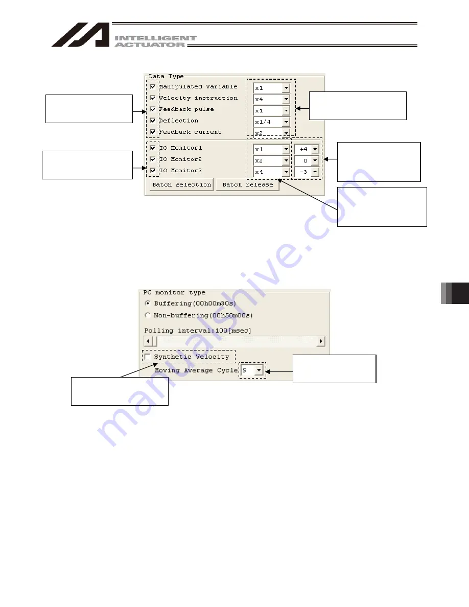
5) Select the data type, output multiplying factor and display offset for the monitor data.
Fig. 11.37
Data Type Select
Note 1 Only those with a check mark being put in IO monitor setting (Fig. 11.32) are available for
setting.
Note 2 Refer to (7) for detail of I/O data graph display settings.
6) Select a monitor type.
Fig. 11.38
PC Monitor Type Setting
[Buffering]
Have the graph displayed by using the data buffering on the controller side.
[Non-Buffering]
Have the graph displayed with data read out at the time of every interval
set in “Polling Interval”.
[Composing Velocity]
Set display on/off of composing velocity of the monitoring applicable axis
(Dedicated for when buffering).
[Movement Average Frequency] Set the movement average frequency with calculation of composing
velocity (Dedicated for when buffering).
Set the composing velocity
display of the monitoring
applicable axis.
Set the movement average
frequency for the
composing velocity.
Put a check mark on the
servo data to monitor.
Put a check mark on the
I/O data to monitor.
(Note 1)
Select the output multiplying
factor for the display of servo
data graph.
Select offset for the
display of I/O data graph.
(Note 2)
Select the output
multiplying factor for the
display of I/O data graph.
(Note 2)
Summary of Contents for IA-101-TT-USB
Page 2: ......
Page 4: ......
Page 8: ......
Page 50: ...1 Before You Begin 42 1 4 Connection to Controller Fig 1 48 X SEL K J Type Controller ...
Page 52: ...1 Before You Begin 44 Figure shows example of TT Fig 1 50 Table Top Actuator TT TTA ...
Page 53: ...1 Before You Begin 45 Fig 1 51 X SEL KX JX Type Controller ...
Page 62: ...1 Before You Begin 54 Fig 1 60 ASEL Type Controller USB Cable ...
Page 63: ...1 Before You Begin 55 Fig 1 61 PSEL Type Controller USB Cable ...
Page 189: ...9 Symbol Edit Window 181 ...
Page 251: ...13 How to Reset an Absolute Encoder 243 Fig 13 38 Arm Length 120 Reference Position ...
Page 386: ...16 Appendix 378 ...
Page 391: ......


