10. Coordinate System Definition Data Edit W
indow
192
10.4 Simple Interference Check Zone
The simple interference check zone is an area set for the purpose of interference check between the robot
and the peripherals. Entry of the center of tool installation surface into the simple interference check zone
can be detected when tool coordinate system No. 0 (= tool coordinate system offsets are 0) is selected,
while entry of the tool end in the simple interference check zone can be detected when tool coordinate
system No. 1 through 127 (= tool coordinate system offset is other than 0) is selected.
(1) Note on using the simple interference check zone
Entry of the center of tool installation surface (when tool coordinate system No. 0 is selected) or tool end
(when tool coordinate system No. 1 through 127 is selected) into the simple interference check zone is
detected. Entry of the circumference of the R-axis or any part of the tool other than the end is not detected.
This function does not prevent entry of the tool into the simple interference check zone. It only detects that
the tool has entered the zone.
Entry cannot be detected reliably unless the applicable part of the tool remains inside the simple
interference check zone for at least 5msec. Accordingly, this function is intended as a simple check during
low-speed operation.
The actual motion differs between high-speed operation (actual operating condition) and low-speed
operation. Provide a sufficient margin to prevent interference. (During high-speed operation, the tool tends
to pass along a line further inward compared with low-speed operation.)
The defined coordinates of the simple interference check zone are always handled as data linked to the
base coordinate system (work coordinate system selection No. 0). Therefore, the position of simple
interference check zone does not change even when the work coordinate system is changed. Exercise
caution. If the defined coordinates of the simple interference check zone are changed, it takes 5msec
before the check result reflects the new settings.
During PTP operation, the tool does not follow specified routes. When operating the tool near an obstacle
(including the robot body), always perform test operation at low speed and confirm that interference does
not occur. Thereafter, gradually increase the speed to an appropriate level.
(2) Setting of simple interference check zone
Set the simple interference check zone using the position data in the base coordinate system.
Enter the maximum and minimum coordinates of the simple interference check zone.
Set the boundaries of the simple interference check zone parallel with the base coordinate axes.
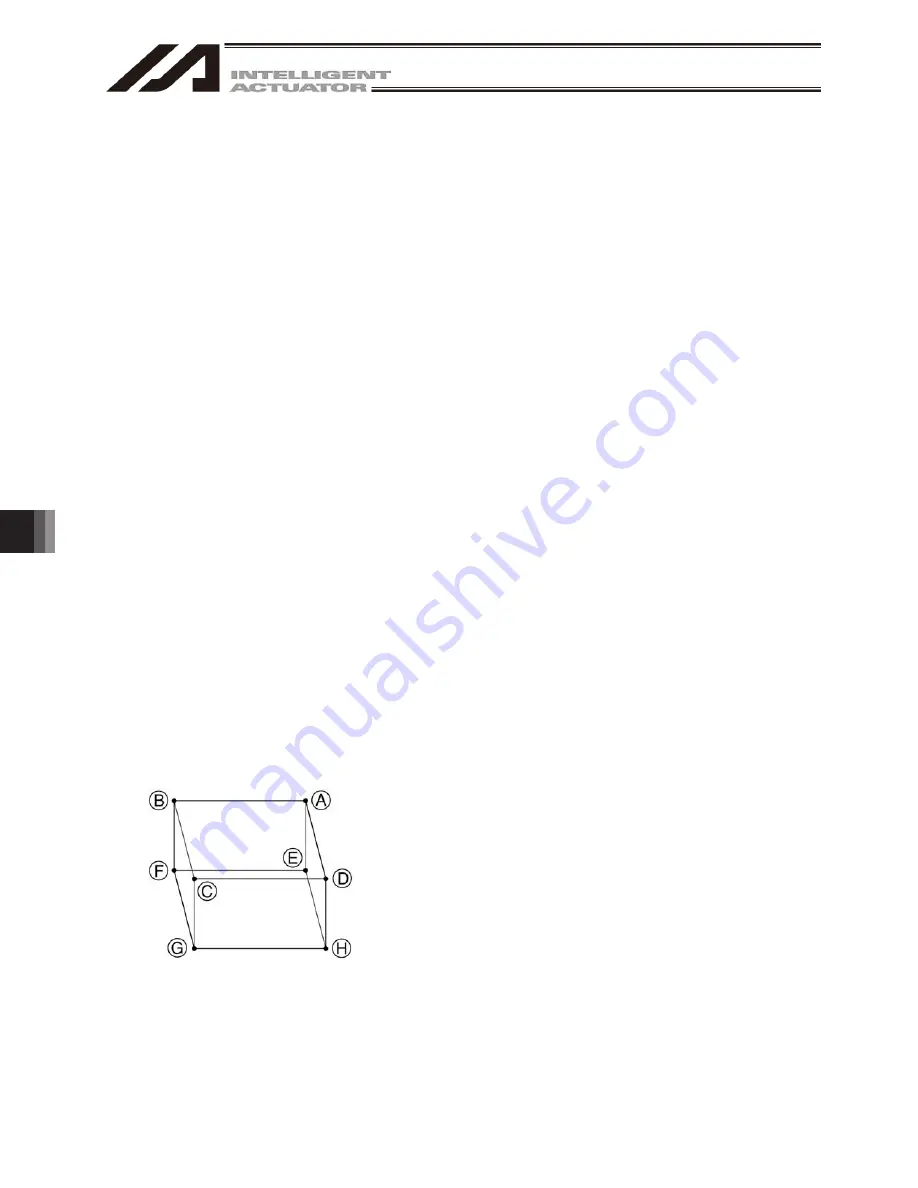
To set the simple interference check zone as a
rectangular solid like the one shown at the left,
enter the coordinates of two points in any one of
the four combinations of A-G, B-H, C-E or D-F.
Summary of Contents for IA-101-TT-USB
Page 2: ......
Page 4: ......
Page 8: ......
Page 50: ...1 Before You Begin 42 1 4 Connection to Controller Fig 1 48 X SEL K J Type Controller ...
Page 52: ...1 Before You Begin 44 Figure shows example of TT Fig 1 50 Table Top Actuator TT TTA ...
Page 53: ...1 Before You Begin 45 Fig 1 51 X SEL KX JX Type Controller ...
Page 62: ...1 Before You Begin 54 Fig 1 60 ASEL Type Controller USB Cable ...
Page 63: ...1 Before You Begin 55 Fig 1 61 PSEL Type Controller USB Cable ...
Page 189: ...9 Symbol Edit Window 181 ...
Page 251: ...13 How to Reset an Absolute Encoder 243 Fig 13 38 Arm Length 120 Reference Position ...
Page 386: ...16 Appendix 378 ...
Page 391: ......


