GE Power Management
ALPS Advanced Line Protection System
2-23
2 CALCULATION OF SETTINGS
2.3 PROTECTION SETTINGS
2
•
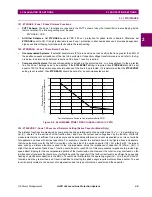
Step Distance Scheme: These functions only work with the pilot channel therefore, when this type of scheme is
selected, they will have no effect regardless of what setting is used for Z2GRDCHAR and what setting is made for
these functions. In simple terms, don’t worry about IPT and IPB if a step distance scheme is selected.
•
PUTT Scheme: The IPT and IPB functions should not be used in this scheme. Therefore, insure that Z2GDCHAR is
set to MHO as proposed under the Z2GDCHAR setting description.
•
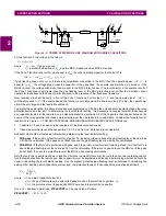
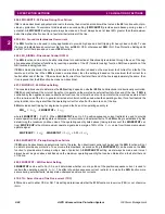
POTT1 Scheme: IPT is logically ANDed with the forward looking negative sequence directional function, NT, to form
the pilot tripping. The IPT operating quantity is:
IPT
op
= 3·
I
0
It is proposed that IPT_PICKUP be set to its minimum value of 0.25 amps. IPB is not used therefore any setting that is
made is irrelevant.
•
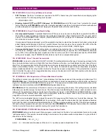
Hybrid and POTT2 Schemes: IPT is logically ANDed with the forward looking negative sequence directional function,
NT, to form the pilot tripping. The IPT operating quantity is:
IPT
op
=
IPB is logically ANDed with the reverse looking negative sequence directional function, NB, to form the pilot blocking
function. The IPB operating quantity is:
IPT
op
= 3·
I
0
- IPBKFACTOR x 3·
I
1
The IPBKFACTOR controls the amount of positive sequence current restraint that is used with the
IPB function. IPBK-
FACTOR can be set equal to 0 or 0.066. A setting of 0.066 is proposed for these schemes. Positive sequence current
restraint is used in both the tripping and blocking functions to provide increased security for any current unbalance that
may occur during load flow or external fault conditions.
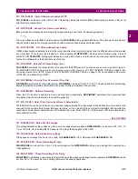
IPT and IPB must be set so as to provide proper coordination. This is done by setting the IPB function more sensitively
than the IPT function. The following settings are proposed:
IPB_PICKUP = minimum
IPT_PICKUP = 1.3 x IPB_PICKUP
R
+
I
oc
where:
IPB_PICKUP
R
= setting of IPB function at remote terminal of transmission line.
I
oc
= zero sequence line charging current (include effect of any non-switched shunt reactors)
•
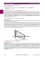
Blocking Scheme: IPT is logically ANDed with the forward looking negative sequence directional function, NT, to form
the pilot tripping function. The IPT operating quantity is:
IPT
op
= 3·
I
0
- (0.3)·
I
1
Positive sequence current restraint is used to provide increased security for any current unbalance that may occur dur-
ing load flow or external fault conditions.
Depending on the CARRSTART setting (1204) described under the SCHEME category, IPB may be:
1.
Logically ANDed with the negative sequence blocking function NB to form the pilot tripping function.
2.
Used alone to form the carrier start function.
3.
Not be used at all in the carrier start circuit.
When IPB is used, either alone or with NB, the operating quantity is
IPT
op
= 3·
I
0
- IPBKFACTOR x 3·
I
1
The IPBKFACTOR controls the amount of positive sequence current restraint that is used with the
IPB function. IPBK-
FACTOR can be set equal to 0 or 0.066. The proposed settings for a blocking scheme are dependent on the
CARRSTART setting and are given below in Table 2–7: PROPOSED SETTINGS FOR BLOCKING SCHEME.
Table 2–7: PROPOSED SETTINGS FOR BLOCKING SCHEME
CARRSTART
IPBKFACTOR
DIR (NB and IPB)
0.066
IPB (IPB alone)
0.0
FD (Fault Detector)
Don’t Care
3
I
0
0.3
I
1
–

