GE Power Management
ALPS Advanced Line Protection System
C-1
APPENDIX C
C.1 OVERVIEW
C
APPENDIX C DNPC.1 OVERVIEW
C.1.1 DESCRIPTION
The DNP Protocol is only available on ALPS Rev. A versions V0004.04AA23 or higher and Rev. B. versions
V0005.01AA02 or higher.
This appendix contains information for using DNP with the ALPS for users familiar with the DNP protocol. Since DNP is a
complex protocol, it is not within the scope of this manual to provide a complete description of its operation in the detail
required for communication with the ALPS. It is strongly recommended that interested users contact the DNP Users Group
at
www.dnp.org
to obtain further information. Members of the DNP Users group are eligible to receive complete descrip-
tions of all aspects of the protocol.
C.1.2 MODIFYING SETTINGS USING DNP
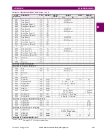
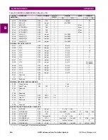
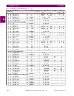
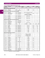
ALPS settings can be read using Function Code 1 to read the Analog Output Object Points. Settings can only be modified
using Function Codes 5 or 6 to Direct Operate the Analog Output Object Points. Since there are eight groups of settings for
most of the Settings categories, the Settings group of interest must be selected before reading or writing any of the Analog
Output Points. Analog Output Point #0 gives the currently active settings group being used by the DNP application in the
device. Note that this is not necessarily same as the currently active settings group of the device. On power-up or any
device restart, this point is set to the active settings group of the device, but this can later be changed using DNP functions
and can be different from the active settings group in the device.
Binary Output #13, Start Settings Change must be activated before starting any settings changes using function codes 5 or
6 to Analog Output points. Any changes to the Analog output points are only done in the local copy of the DNP application
and are not written to the Non-Volatile memory section of the device where settings are stored till Binary Output #14, End
Settings Change is activated. This procedure is summarized in the following steps.
1.
Start Settings change by activating Binary Output #13 (using function code 5 or 6)
2.
Select the settings group by writing the appropriate value in Analog Output point #0
(using function code 5 or 6).
3.
Modify the required settings by writing to the corresponding Analog Output points
(using function code 5 or 6).
4.
End Settings change by activating Binary Output #14 (using function code 5 or 6). When this is done, the new settings
are saved in Non-Volatile memory and the device is restarted if any of the critical settings are modified. Refer to the
Instruction Book for details on the Critical settings.
NOTE


