GE Power Management
ALPS Advanced Line Protection System
8-3
8 LOCAL USER INTERFACE
8.1 INTRODUCTION
8
d) DATA ENTRY KEYS
The numeric keys 1 and 3 have two meanings depending on the context of their use. If the user is entering numeric values,
the [1/Y] and [3/N] keys are used as the numbers 1 and 3. If the user is responding to a YES/NO prompt, the [1/Y] key is
interpreted as YES and the [3/N] key is interpreted as NO.
The [INV] (!) key is used to invert the values of logic signals used with the programmable outputs. For example, if you need
to invert the value of the ZONE 1 AG logic signal (signal number 81) for input into programmable output A1, enter [INV] fol-
lowed by “81” (display: !81).
8.1.4 MESSAGES
All messages on the display are the result of some keypad action, with four exceptions: the Trip message when the relay
has caused a protective trip, the Fail message when the relay has discovered a critical self-test failure, the Warning mes-
sage when the relay has discovered a non-critical self-test failure, and the Initialization messages when the relay is initializ-
ing during a power up.
If a protective trip occurs when there is no self-test message (Self-test Failure or Warning) on the display, the TRIP mes-
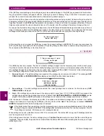
sage will be displayed on four lines of the display. An example is shown below:
The TRIP message will be displayed with the background flashing to indicate that the relay has caused a protective trip.
The red trip LED will also be flashing to indicate the trip, and that the trip has not been acknowledged. Three fields of infor-
mation form the trip message on display. They are: a three character fault type (for example, ABG), a three character trip
type (see Section 8.2.3: REQUEST FAULT INFORMATION on page 8–17 for a list of the trip types), and distance to the
fault (in the user-specified units). The message will remain on the display until removed by a keypad operation or by the
remote communications Target Reset command. If the relay restarts or is powered down and up, the trip indicator will be
remembered and redisplayed. In either case, as soon as any key on the keypad is pressed or remote communications
resets the target, the LED indicating protective tripping by the relay will stop flashing and the Trip message will be removed
from display. The Trip information will be stored for later use.
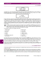
When a system failure occurs, the Fail message is always shown on the bottom two lines of the display. It has the following
format:
BBB FAIL–XXXXXXXXXXXXX
XXXXXXXXXXXXXXXXXXXXXX
where
BBB stands for the sub-system name issuing the message, and XXX...XXX is the text which describes the critical
self-test failure. The Fail message remains on the display until a key is pressed or until the relay restarts successfully (with
no self-test failures).
If a trip message is already on display when a failure occurs, the trip message is displayed on a single line (top line) instead
of on all the four lines. The fail message is still shown on the bottom two lines of the display, as shown below:
Since a trip has occurred, the LCD background for all four lines will be flashing.
Warning messages are always shown on the bottom two lines of the display using the same format as failure messages.
The warning message remains on the display until a key is pressed or until the relay restarts successfully (with no self-test
warnings). If a trip message is already displayed when a warning occurs, the display format will be the same as the fail
message. Since a trip has occurred, the LCD background will be flashing.
Initialization messages are displayed while the relay is initializing during a power-up (but not during a warm restart). All
other messages are the result of keypad operations and remain until another key is pressed or until no keys have been
pressed for a period of 15 minutes. At the end of this time-out interval, the display is blanked.
TRIP
AG
Z1
50.5 MI
TRIP AG Z1 50.5MI
BBB FAIL-XXXXXXXXXXX
XXXXXXXXXXXXXXXXXXXX

