GE Power Management
ALPS Advanced Line Protection System
2-19
2 CALCULATION OF SETTINGS
2.3 PROTECTION SETTINGS
2
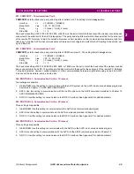
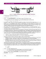
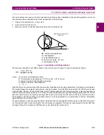
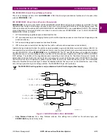
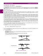
For example, consider the fault at F1 shown below and assume that a blocking scheme is being used in the protected line.
A continuous blocking signal must be sent to the remote terminal to block tripping there until the fault is cleared. Offset in
the Zone 4 functions will assure this condition. Offset will also assure that Zone 4 time delayed backup (when used) will
also be provided for zero voltage faults.
Figure 2–10: ZONE 4 FAULT EXAMPLE
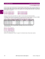
The ALPS Zone 4 phase distance functions are not provided with offset since they use an adaptive memory feature to pro-
vide the operation needed for bolted three-phase faults at the relay location. The adaptive memory works as follows:
1.
If the fault voltage is less than 10% of rated voltage then the voltage prior to the fault will be used to polarize the Zone
4 functions. This voltage will be held, and the functions will remain picked up, until the fault is cleared, at which time
they will reset.
2.
If the voltage is greater than 10% of rated voltage, then the voltage prior to the fault will be held for 5 cycles and will
then revert to the actual fault voltage. The functions will stay picked up for the duration of the fault and will reset when
the fault clears.
In either case, the functions will provide a continuous output for the duration of the fault and will thus meet the requirements
of the particular application.
401: Z4PHASE - Z4 Phase Distance
Z4PHASE can be set to YES or NO and determines whether Zone 4 phase distance functions are used in the application.
•
Blocking, Hybrid and POTT2 Schemes: The Zone 4 phase distance functions are always required in these schemes;
therefore, set:
Z4PHASE = YES
•
Step Distance and POTT1 Schemes: If the Zone 4 phase distance functions are to be used to provide time delayed
backup protection, then set Z4PHASE = YES; otherwise, set Z4PHASE = NO.
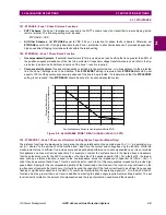
402: Z4PHREACH - Z4 Phase Distance Reach
•
Blocking, Hybrid and POTT2 Schemes: In a blocking scheme, the Zone 4 functions key the transmitter to send a
blocking signal to the remote terminal of the line to block tripping for an external fault (F1, for example) within reach of
the Zone 2 functions located at the remote terminal.
In a hybrid scheme, the Zone 4 functions prevent keying of the transmitter to block echoing of the trip signal received
as a result of the operation of the remote Zone 2 functions for an external fault (at F1 for example) within their reach.
In a POTT2 scheme the Zone 4 functions establish transient blocking circuitry to prevent tripping during fault clearing
and fault current reversals.
In all of these schemes, it is imperative that the blocking functions be set with a reach that will allow them to see all
faults that the remote Zone 2 functions will see. The following guidelines are proposed:
1.
If the reach of the Zone 2 phase distance function (Z2PHREACH
R
) at the remote end of the line is less than
twice the positive-sequence impedance of the line, then the proposed setting is:
Z4PHREACH = 0.85 x Z2PHREACH
R
2.
If the reach of the Zone 2 functions at the remote end is greater than twice the positive-sequence impedance
of the line, then the proposed settings are:
Z4PHREACH = 1.7 x (Z2PHREACH
R
-
Z
1
L
)
where:
Z2PHREACH
R
= reach of phase Zone 2 functions at remote line terminal
Z
1
L
= positive sequence impedance of protected line
With these proposed settings, proper coordination will be obtained between the tripping and blocking functions at the
remote terminal of the line. It may be possible to use a shorter setting or a longer setting than proposed, but:
B
A
Z2A
Z4B
PROTECTED LINE
F1

