GE Power Management
ALPS Advanced Line Protection System
13-1
13 XPRESSION BUILDER
13.1 INTRODUCTION
13
13 XPRESSION BUILDER 13.1 INTRODUCTION
13.1.1 OVERVIEW
The ALPS relay has been designed to allow flexibility in the operation of contact converter inputs and contact outputs. The
inputs and outputs are not hard-wired to any function; the functions of each input and output are defined by a software file
which is downloaded to the relay as a part of each setting group.
The software file represents the linkage between the contact converters, internally generated protection flags, and contact
outputs; it contains information regarding the logical relationships among each entity. This file is built using a windows
based application called Xpression Builder.
Xpression Builder allows the utility engineer to design the interconnection of the inputs and outputs with Boolean operators,
latches, timers, and counters in a graphical environment. The application performs the task of compiling the design from a
graphical format, and allows the engineer to download the file to a relay setting group with ALPS-Link. Each setting group
can contain different Xpression Builder logic. The ALPS comes with a default Configurable Logic implementation.
13.1.2 INSTALLATION
If the ALPS software suite has been installed from the Products CD or GE Power Management website, Xpression Builder
is probably already installed. To install Xpression Builder by itself from the Products CD or website, consult the procedure in
Section 11.1.5 SOFTWARE INSTALLATION on page 11–3, and choose Xpression Builder from the ALPS software menu.
To install the software from the GE Power Management web site enter the following URL in your Web browser:
www.GEindustrial.com/pm
The home page is the same as that shown in Figure 11–2: GE POWER MANAGEMENT WELCOME SCREEN on page 11–
3. Follow the procedure in Section 11.1.5 SOFTWARE INSTALLATION on page 11–3 to continue the installation.
13.1.3 DESIGN CONSIDERATIONS
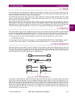
Xpression Builder logic is processed every other millisecond. This should be considered when designing logic to implement
in the relay. The more gates connected in series, the longer the time delay from the initial logic input to the final logic output
(roughly 2 ms per gate) of the expected result. This delay applies to the Xpression Builder logic only. The scheme logic out-
puts of the relay will not be delayed with the use of configurable logic.
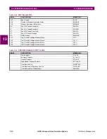
Figure 13–1: LOGIC PROCESSING DELAY
For example, the TRIP (flag #33) output of the scheme logic, when directly connected to an output contact, will close that
contact when it becomes high (logic 1) with no additional processing delay as shown in part A of the figure above. If the
TRIP flag is connected to a Boolean gate before it reaches an output contact, a gate processing delay of 2 ms should be
added to the expected function operating time as shown in part B above. This should be taken into consideration in the
design of the relay configurable logic. This is why it is recommended all user defined logic be tested in a laboratory environ-
ment before installation in the field. This will ensure user confidence and expected performance of the configurable logic
developed with the relay internal flags.
P U ~ 2 m s
D O ~ 2 m s
(A)
(B)
Trip
T 1
(A)
Trip
T 1
(B)
input always low (logic 0)
P U
D O
Trip
Trip
T1
T1

