2-24
ALPS Advanced Line Protection System
GE Power Management
2.3 PROTECTION SETTINGS
2 CALCULATION OF SETTINGS
2
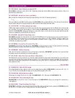
505: IPBKFACTOR - IPB I1 Restraint
The IPB operating quantity is:
IPB
op
= 3
·I
0
– IPBKFACTOR x 3·
I
1
The IPBKFACTOR controls the amount of positive sequence current restraint that is used in the IPB function. IPBKFAC-
TOR can be set to 0 or 0.066. Please refer to the description under the IPB_PICKUP setting to determine the IPBKFAC-
TOR setting to be used.
506: NT_OFFSET: NT/NB Offset
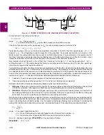
The NT/NB functions use an offset to provide a reliable polarizing quantity for the conditions shown in Figure 2–11: NT/NB
FUNCTIONS. Shown in this Figure are the negative sequence networks and corresponding voltage profiles for an uncom-
pensated system and a system using series capacitors.
In the uncompensated system, the voltage (
V ) at the relay is in the proper direction to provide correct directional sensing,
but, depending on the source to line impedance ration (Zs/ZL), the magnitude of the voltage may not be sufficient to provide
a reliable polarizing quantity. The problem is most onerous on a long transmission line with a strong source impedance
behind the relay (Zs/ZL is quite small). The effect of the offset in this case is to add a component to the actual voltage so as
to replicate the voltage at a point some distance down the transmission line.
In the system with series capacitors, and with line-side potential as shown in Figure 2–11: NT/NB FUNCTIONS on page 2–
24, the effect of the capacitor is to cause the voltage to reverse as shown. This will lead to incorrect directional sensing
unless something is done to overcome the reversal. The offset in this case provides a compensating voltage that is oppo-
site to and larger than the drop in the capacitor so that when it is added to the actual voltage a signal is produced that is in
the proper direction to provide correct directional sensing.
If bus-side potential is used, the voltage will never reverse and, as is done for an uncompensated line, it is only necessary
to use an offset setting that is sufficient to cause a reliable polarizing source.
NT_OFFSET is a per unit impedance setting. The base ohms for this setting is:
, where
I
n
= Magnetics Module CT rating (1A or 5A)
Use the values determined as follows and make the next lowest available setting. For example, if the calculated value is
0.027, set NT_OFFSET = 0.02.
1.
Uncompensated Lines
NT_OFFSET should be set to 0.05, or the value determined by the following if it is less than 0.05:
NT_OFFSET = (0.005)·(
Z
1
)·(
I
n
)
where
Z
1
= positive sequence impedance of protected line (in secondary ohms)
I
n
= Magnetics Module CT rating (1A or 5A)
Figure 2–11: NT/NB FUNCTIONS
100
I
n
----------
Zs
ZL
Xc
V
F
V
Vf
Xc > Zs
Zs
ZL
Xc
F
V
Vf
Xc > Zs
Uncompensated System:
Series Compensated System:
Bus-
side
Line-
side

