GE Power Management
ALPS Advanced Line Protection System
6-9
6 FUNCTIONAL TESTS (USER SETTINGS)
6.4 BACKUP PROTECTION TESTS
6
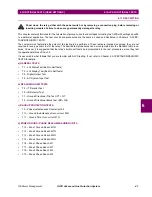
6.4.3 T11 – GROUND TIME OVERCURRENT 51G
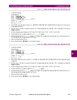
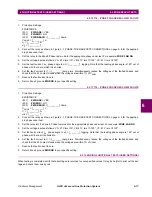
1.
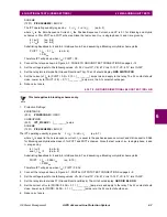
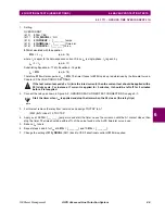
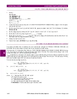
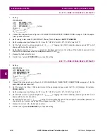
Setting:
OVERCURRNT
(610)
51G = YES
(611)
51G_DIRCNL = NO
(612)
51GPICKUP = [_________] amps,
(615)
51GTIMDIAL = [________] Time dial,
(614)
51GCURVE = [________] Curve,
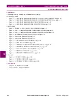
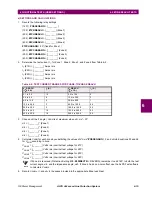
51G is calculated with the equation
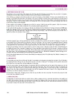
51G =
(eq. 6–16)
where
I
0
is equal to the zero-sequence current. Since
I
op
is single-phase,
I
0
is given by
I
op
/ 3 =
I
0
.
(eq. 6–17)
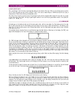
Substituting Equation 6–17 into Equation 6–16 yields
I
op
= 51G
.
(eq. 6–18)
Therefore, 51G will pick up when
I
op
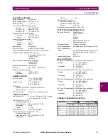
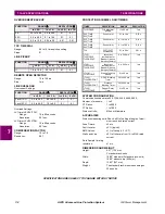
= 51G. The time it takes for 51G to pick up is determined by the time-dial curve in
Chapter 2: CALCULATION OF SETTINGS.
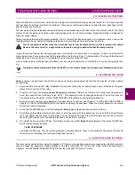
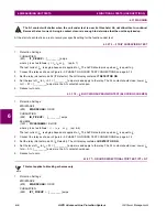
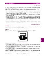
If the test current exceeds 2 x
In (In is the rated current), then the current test should be applied with a
50% duty cycle. For instance, if current is applied for 5 minutes, it should be left off for 5 minutes
before it is reapplied.
2.
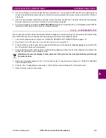
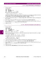
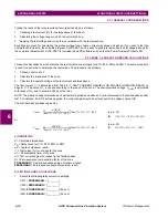
Connect the relay as shown in Figure 5–2: GROUND REACH TIMER TEST CONNECTIONS on page 5–7.
Start the timer when
I
op
is applied and stop the timer when the A1 closes (the relay trips).
3.
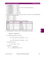
For this test remove the relay from test mode and assign TOCTRP to A1.
(2007) A1 = index 119, TOCTRP
4.
Apply
I
op
at 2·51G = [________] amps rms and start the timer. Leave the current on until the A1 contact closes, then
stop the timer. The time should be within ±7% of the value found on the ALPS time-dial curve in use.
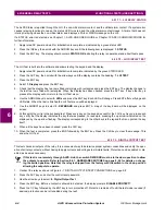
5.
Reduce
I
op
to zero.
6.
Repeat steps 4 and 5 for
I
op
at 6·51G = [________] and 10·51G = [________].
7.
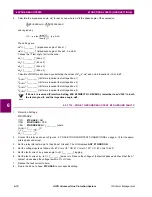
Change the setting of 51G_DRCNL (0611) back to YES if directional control of 51G is required.
3
I
0
×
CAUTION
NOTE


