


5-16
ALPS Advanced Line Protection System
GE Power Management
5.4 PHASE-TO-PHASE ZONE REACH TESTING
5 FUNCTIONAL TESTS (FACTORY SETTINGS)
5
4.
Set the fault current,
I
op
, to the phase-angle value listed below. Note that the leading phase angle is 180° out of phase
with the line to which it is shorted. (increase VA, VB, and VC to 75 V when
∠
I
op
= –55°).
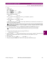
5.
Set the fault current to 3.3 (0.7) amps rms. Simultaneously reduce the voltages of the faulted phases and check that
the A1 contact closes when the voltages are within the limits shown in the table above.
6.
Reduce the fault current to zero. Note that the trip target indication concurs with the fault. For example, an AB fault is
displayed as follows: TRIP AB Z4 “DIST”, where “DIST” is the displayed target.
7.
Repeat the test for phase BC and CA faults.
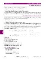
5.4.5 T20 – PHASE (ZONE BACK-UP) TIMER TESTS
1.
For this test remove the relay from test mode and record the pre-test values for all Protection settings used in this test.
2.
Protection Settings:
Z1DISTANCE
(101)
Z1PHASE= NO
(104)
Z1GROUND = NO
Z2DISTANCE
(201)
Z2PHASE = YES
(204)
Z2GROUND= NO
(209)
Z2P_TIME = 1.0
(210)
Z2G_TIME = 1.0
Z3DISTANCE
(301)
Z3PHASE = YES
(304)
Z3GRND = NO
(307)
Z3P_TIME = 3.0
(308)
Z3G_TIME = 3.0
Z4DISTANCE
(401)
Z4PHASE = YES
(405)
Z4GRND = NO
(410)
Z4P_TIME = 5.0
(411)
Z4G_TIME = 5.0
OVERCURRNT
(601)
50 = NO
(605)
50G = NO
(610)
51G = NO
OS BLOCKING
(1603)
BLOCKWHAT = 3 (BLKNONE)
OUTPUTS
(2007)
A1 = Z2PTMR; Index 132
a) ZONE 2 TIMER
3.
Connect the relay as shown in Figure 5–3: PHASE-REACH TIMER TEST CONNECTIONS on page 5–18 for an AB
fault.
4.
Set the voltage inputs as follows: VA: 55 V rms
∠
0°, VB: 55 V rms
∠
–120°, VC: 67 V rms
∠
+120°.
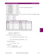
5.
Set the phase angle of the fault current,
∠
I
op
, to –55°.
I DEGREES
VOLTS RMS
DISPLAYED TARGET
†
–25
56 to 63
–
–55
64 to 72
290 to 310
–85
56 to 63
–
†
Reference only