2-2
ALPS Advanced Line Protection System
GE Power Management
2.2 GENERAL SETTINGS
2 CALCULATION OF SETTINGS
2
2.2 GENERAL SETTINGS
2.2.1 CONFIGURATION
101: UNITID - Unit ID Number
The UNITID is a decimal number between 0 and 9999 that uniquely identifies an ALPS relay system. When the ALPS sys-
tem is accessed via one of the serial ports the UNITID must be known to establish communication, thus providing an addi-
tional measure of security. UNITID can only be changed via the keypad. It is not possible to change UNITID via the ALPS-
Link communications program.
102: SYSFREQ - System Frequency
SYSFREQ establishes the operating frequency of the ALPS. It can be set to either 50 Hz or 60 Hz. When this setting is
changed it will only be implemented after turning the DC power off and then on.
103: PHASRROTATE - Phase Rotation
PHASRROTATE can be set to either ABC or ACB to match the positive-sequence phase rotation for the power system
where the ALPS is installed. This setting permits proper reporting of the faulted phase or phase pair.
104: TIMESYNCH - Select Time Synchronization
TIMESYNCH determines the method of synchronizing the ALPS internal clock. It can be set to 0 (INTERNAL) or 1
(IRIG-B). TIMESYNCH = 0 lets the clock run freely from the internal oscillator. TIMESYNCH = 1 synchronizes the clock
using an IRIG-B signal connected directly to the ALPS system via the assigned port.
105: NUM_BKR - Number of Breakers
NUM_BKR can be set to either 1 or 2. When set to 1, the TRIP and CLOSE commands can only be used to activate the
BREAKER 1 trip and close outputs. When set to 2, the TRIP and CLOSE commands can selectively be used to activate
either the BREAKER 1 or BREAKER 2 outputs. When a POTT or PUTT scheme is selected, this setting also determines
whether 52/b contacts from one breaker or two breakers are used to key the transmitter with the breaker(s) open.
106: NUM_TC - Number of Trip Circuits
The number of trip outputs is dependent on whether the three phase or single phase tripping model is used. Assignment of
the trip outputs is made via the NUM_TC setting and is directly coupled to the NUM_BKR setting.
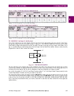
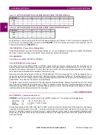
With the Single Phase Tripping model, six outputs (T1 to T6) are available and assigned per the NUM_TC setting as shown
in Table 2–1: NUM_TC SETTING (SINGLE PHASE MODELS). In this case, outputs T4 to T6 are available for assignment
with Xpression Builder only when one breaker with one set of trip coils is being controlled (NUM_TC = 1).
With the Three Phase Tripping model, four outputs (T1 to T4) are available for tripping and assigned per the NUM_TC set-
ting as shown in Table 2–2: NUM_TC SETTING (THREE PHASE MODELS). If one breaker with a single trip circuit is being
used (NUM_TC = 1), then outputs T2 to T4 are available for assignment to different tasks through Xpression Builder. Out-
puts T3 and T4 are used only if two breakers are being controlled and if each of the breakers has two independent trip cir-
cuits (NUM_TC = 2). If independent trip coils are not being used, then the T3 and T4 contacts can be re-assigned with
Xpression Builder.
The ALPS has the capability (when enabled) to trip the breaker(s) locally through the keypad or remotely via the ALPS-Link
program or ASCII commands. In order for the ALPS to recognize which breaker should be tripped, the NUM_TC setting
must be made as given in Table 2–1: NUM_TC SETTING (SINGLE PHASE MODELS) or Table 2–2: NUM_TC SETTING
(THREE PHASE MODELS) and the trip outputs must be connected to the appropriate trip coils as assigned in the tables.
For example, if a three-pole tripping scheme is employed and if NUM_TC = 2, then trip output T1 must be connected to the
trip coil TC-1 of breaker number 1 and the output T2 must be connected to the trip coil TC-1 of breaker number 2.


