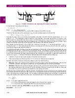
GE Power Management
ALPS Advanced Line Protection System
2-13
2 CALCULATION OF SETTINGS
2.3 PROTECTION SETTINGS
2
2.3.2 ZONE 2, ZONE 3, AND ZONE 4 DISTANCE FUNCTIONS
The reach setting to be used on the Mho type distance functions will be established by the specific application. It must not
exceed the maximum allowable reach which is dependent on the following:
1.
Shape of the characteristic – circle or lens,
2.
Angle of maximum reach, and
3.
Maximum amount of load flow transferred across the transmission line.
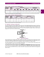
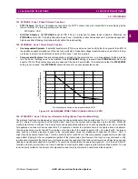
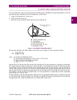
Figure 2–5: MAXIMUM ALLOWABLE REACH
The maximum allowable reach (
MR) is based on the criteria shown in Figure 2-4 and is calculated as follows:
where
Z
L
= minimum load impedance (ohms)
B = Characteristic angle (degrees) = 90
°
for a circle; > 90
°
for a lens
C = angle of minimum load impedance (degrees)
D = angle of maximum reach (degrees)
Note that this is the maximum reach that can be safely made based on the given parameters. It is based on maintaining a
40
°
margin between the angles B and A shown in the figure above. A circular Mho characteristic (
B = 90
°
) should be used
when possible. However, for larger load flows (smaller load impedances) and for longer reaches, it may be necessary to
resort to a lenticular characteristic (
B > 90
°
) to remain within the allowable limit. Lenticular settings greater than 120
°
should
never be used. Similarly, the characteristic angle should never be set less than 90
°
except in the case of the Zone 4 func-
tions applied as blocking functions in available schemes. In those applications, it is permissible to set the characteristic
angle for Zone 4 to a minimum of 80
°
.
For each application, a desired reach should be determined then checked against the
MR using a circular Mho characteris-
tic. If the desired reach is less than the
MR, then the setting is acceptable. If the desired reach is greater than the MR, then
the angle
B should be increased until MR equals, or just exceeds the desired reach.
X
R
B
C*
D*
MR
MR = Maximum Allowable Reach
D = Angle of Maximum Reach
C = Load Impedance Angle
*Measured counterclockwise
from R axis
ZL
ZL = Load Impedance
A
B = Characteristic Angle; < 90 = Lens
MR
B
40
°
–
(
)
Z
L
×
sin
220
°
B
–
E
–
(
)
sin
----------------------------------------------
=
E
D
C
–
=

