GE Power Management
ALPS Advanced Line Protection System
2-15
2 CALCULATION OF SETTINGS
2.3 PROTECTION SETTINGS
2
204: Z2GROUND - Zone 2 Ground Distance Function
The choice of settings is YES or NO. Set Z2GROUND = YES if the Zone 2 ground distance functions are to be used, other-
wise set Z2GROUND = NO.
205: Z2GRDCHAR - Zone 2 Ground Function Characteristic
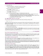
Z2GRDCHAR can be set to either MHO, GDOC, MHOGDOC, MHO2GDOC (single phase models only) or QUAD. This set-
ting determines the type of measuring unit used for the Zone 2 ground distance functions and the pilot tripping zone. The
distance function may be set as an Mho (MHO, MHOGDOC, and MHO2GDOC) or as a quadrilateral (QUAD). The following
ground directional overcurrent functions are placed in service whenever Z2GRDCHAR is set to MHO, MHOGDOC,
MHO2GDOC, GDOC, or QUAD:
1.
NT: forward looking negative-sequence directional function
2.
IPT: zero-sequence overcurrent tripping function (with or without positive-sequence current restraint, depending on the
protection scheme)
3.
NB: reverse looking negative-sequence directional function
4.
IPB: zero-sequence overcurrent blocking function (with or without positive-sequence current restraint)
Instead of using a distance function, the pilot zone may be applied in a ground directional overcurrent scheme (GDOC); it is
also possible to use both the mho ground distance function and the ground directional overcurrent pilot schemes simulta-
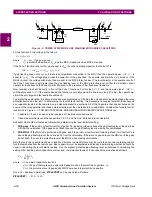
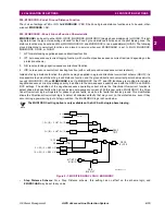
neously (MHOGDOC). When Z2GRDCHAR is set to MHO2GDOC, the IPT and IPB functions are modified to include a
negative-sequence current operating quantity in addition to the zero-sequence quantity used with the GDOC and MHOG-
DOC settings. The addition of the negative-sequence operating current allows the Directional Overcurrent function to
detect phase-to-phase faults which do not include zero-sequence current. With this new option, MHO2GDOC, the Direc-
tional Overcurrent logic will operate for phase to phase faults, as well as for faults that involve ground. This modification
allows the Directional Overcurrent logic to detect all unbalanced faults that may occur on the protected line, even if they
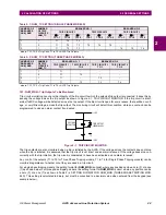
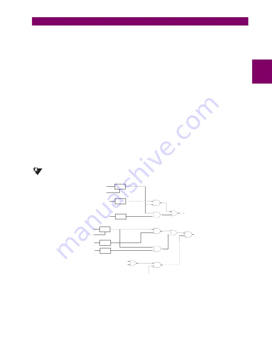
occur during a power swing (out-of-step) condition. The MHO2GDOC logic is shown below.
The MHO2GDOC setting option is only available on the ALPS with single phase tripping.
Figure 2–7: MODIFIED GDOC LOGIC, MHO2GDOC
•
Step Distance Scheme: For a Step Distance scheme, this setting has no affect on the scheme logic, and
Z2GRDCHAR may be set to any value.
NOTE
I2, V2
N T
2
IPT-0
3
×
|I0| – 3
×
KT0
×
|I1|
I2, V2
N B
3
IPB-0
3
×
|I0| – 3
×
KB0
×
|I1|
M T / M T G
M 1 / M 1 G
G D O C
T R I P
G D O C
B L O C K
F D
F D
B I A S A D J U S T
BIAS
A D J U S T
IPT-2
1.5
×
|I2| – 3
×
KT2
×
|I1|
1
3
1
5
2
4
IPB-2
1.5
×
|I2| – 3
×
KB2
×
|I1|
6
O S B
B L K D I S T
M H O 2 G D O C . v s d


