13-10
ALPS Advanced Line Protection System
GE Power Management
13.3 CREATING XPRESSION BUILDER LOGIC
13 XPRESSION BUILDER
13
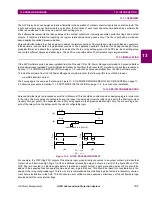
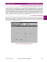
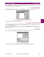
Figure 13–8: INVERTED CC INPUTS
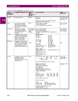
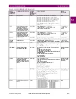
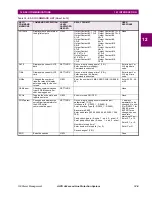
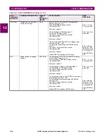
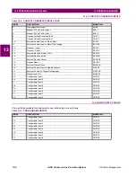
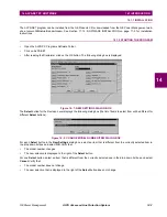
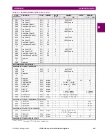
The next step is to take advantage of the internal protection flags in the relay, and put them to work in logical combinations
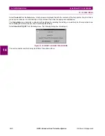
necessary to your specific application. Select the Input flags icon as shown below. The input flags are listed by group
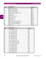
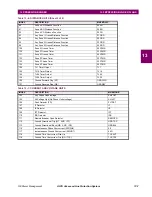
beginning with Table 13–3: CONFIGURABLE INPUTS. You can move between groups by using the mouse to scroll through
the pull-down menu. Simply select the flag by clicking the left mouse button. Move the cursor to the location where the flag
is going to be used and click the left mouse button again. This action will place the flag at the desired location.
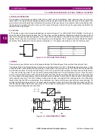
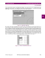
Figure 13–9: INPUT, OPERATOR, AND OUTPUT ICONS
Select the Operator icon as shown above. The available operators are AND, OR, NOT, Latches, Counters, PD Timers, and
Timers. Simply select the operator by clicking the left mouse button. Move the cursor to the location where the operator is
going to be used and click the left mouse button again. This action will place the operator at the desired location.
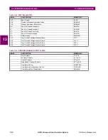
The next step is selecting the output contacts which will be used in the relay application. Select the Output flag icon as
shown above. The output contacts are listed in Table 13–9: USER DEFINABLE OUTPUT FLAGS. Select the output flag by
clicking the left mouse button. Move the cursor to the location where the flag is going to be used and click the left mouse
button again. This action will place the flag at the desired location.
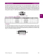
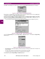
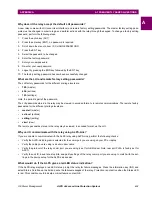
Start connecting the inputs to the Boolean operators and to the output gates. To use straight line connections, select the
Connection icon as shown below. To use orthogonal line connections, select the Orthoconnection icon as shown in
below. Once the type of connection is selected, click the left mouse button on an input or Boolean operator output connec-
tion stud. Move the mouse and click the left button on the connection stud of an output or the input of a Boolean operator.
If all the inputs are connected to logic gates and/or output contacts, the logic is ready for compilation.
Figure 13–10: STRAIGHT AND ORTHO-CONNECTION ICONS

