DRIVE CONFIGURATION
Setting Operating Parameters
48
Setting Operating Parameters
Enter Required Parameters Before Starting VFD
1.
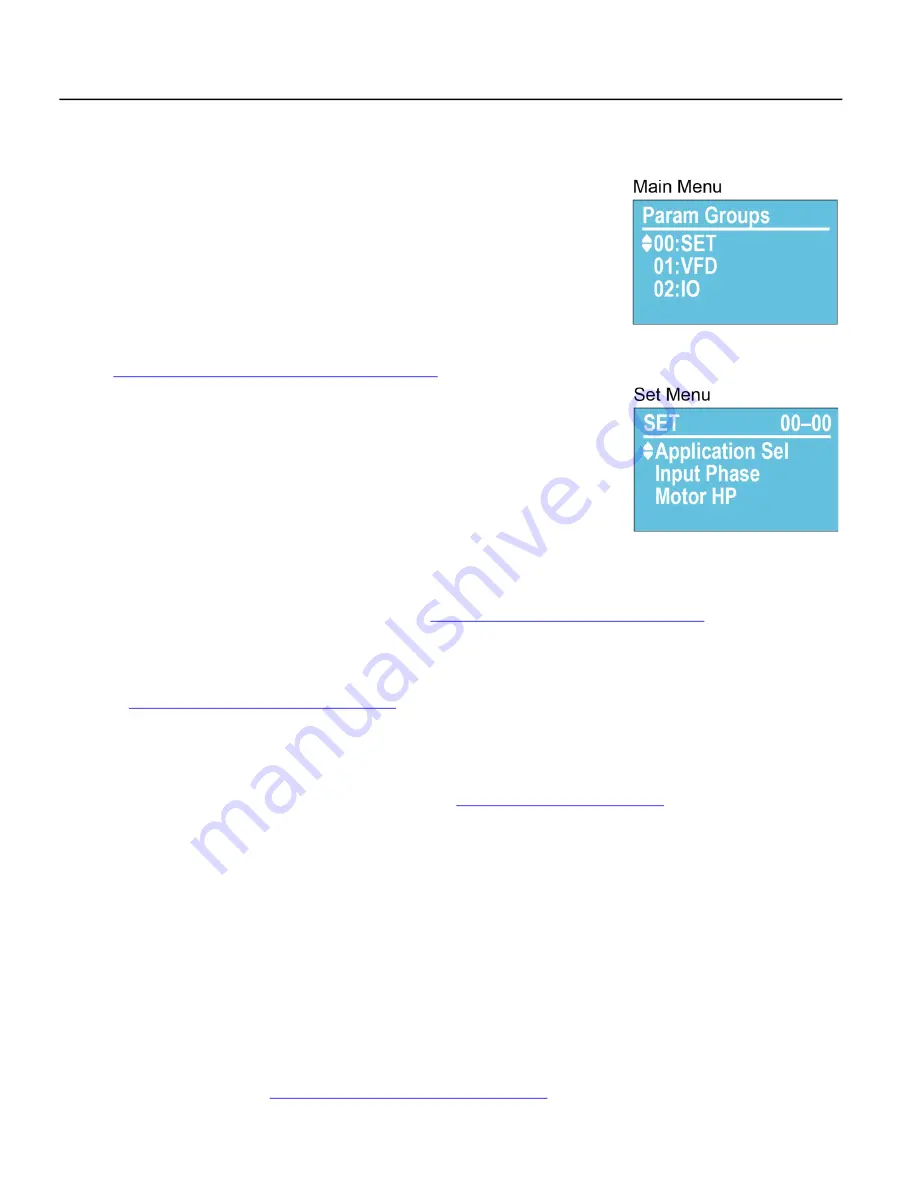
Application Sel [SET–00]:
Use the keypad to select the type of application the drive will
control. When a selection has been made, application related parameters will be auto
-
matically updated to proper defaults. Enter the following parameters to ensure best per
-
formance for the specific installation.
NOTE:
The
BASIC
application provides standard VFD control with start/stop command
from digital inputs and speed reference from a remote analog signal. For systems using a
transducer or other control sensors, choose the relevant application type to ensure that
correct defaults are set.
NOTE:
When using a
FE MagForce
or other permanent magnet motor application, refer to
“Operation with Permanent Magnet Motors” on page 97
2.
Input Phase [SET–01]:
Verify that the setting matches the type of power supply. Default
= 3-phase.
3.
Motor HP [SET–02]:
Enter the rated horsepower from the motor nameplate.
4.
Motor FLA (SFA) [SET–03]:
Enter the FLA (Full Load Amps) rating from the motor
nameplate, or enter SFA (Service Factor Amps) if using a submersible pump motor.
5.
Motor RPM [SET–04]:
Enter the rated motor RPM from the motor nameplate.
6.
Motor Voltage [SET–05]:
Enter the rated voltage from the motor nameplate.
7.
Motor Freq Sel [SET-06]:
Select the standard motor frequency (either 50 or 60 Hz).
Verify Default Settings
After the initial parameters have been entered, the following default settings should be checked and, if nec
-
essary, adjusted to ensure expected operation. Refer to the
“Default Settings Table - SET Menu” on page 50
for a list of automatically populated settings per application.
1.
VFD Max Freq [VFD–00]:
The highest frequency (speed) allowable. If running a FE MagForce pump,
this should be set to the calculated electrical frequency corresponding to the target pump RPM. Refer
to
“Setup FE MagForce Pump Motor” on page 98
2.
VFD Base Freq [VFD–02]:
This should be set to the motor nameplate frequency rating.
3.
Auto Speed Ref [SET–07]:
This is the source of frequency (speed) setpoint the drive will use when in
Auto mode.
•
When using one of the analog inputs with an automated BAS, BMS, or PLC system, be sure to con
-
figure the terminal for the correct signal type. Refer to
“Terminal Identification” on page 41
•
When using feedback from a sensor or transducer, select PID Output. When PID mode is selected,
additional parameters must be verified for setpoints, inputs, and limits.
•
When set to Keypad, the drive will run at the Keypad Speed Reference (F on display).
4.
Auto Run Cmd [SET–08]:
The source of RUN command when VFD is in Auto Mode—Keypad or exter
-
nal.
5.
Hand Speed Ref [SET–09]:
The source of frequency (speed) setpoint the drive will use when in Hand
mode. PID is disabled in Hand mode. Be sure to configure any selected input terminals for the correct
signal type.
•
When set to Keypad, the drive will run at the Keypad Speed Reference (F on display).
6.
Hand Run Cmd [SET–10]:
The source of RUN command when VFD is in Hand Mode—Keypad or exter
-
nal.
7.
Accel Time [SET–11]:
The time in seconds for drive to ramp up from stop to maximum frequency. Rec
-
ommended defaults are 2 seconds for submersible pump motors and 20 seconds for most other appli
-
cations. Additional acceleration curves can be added for more precise control through selected
frequency ranges. Refer to
“Acceleration/Deceleration Control” on page 80
.
Summary of Contents for CERUS X-DRIVE CXD-003A-4V
Page 2: ......
Page 3: ...CERUS X DRIVE INSTALLATION AND OPERATION MANUAL Firmware Version 1 2 Franklin Electric Co Inc ...
Page 96: ...OPERATION Protection Features 96 ...
Page 112: ...ADVANCED APPLICATION OPTIONS Multi Drive Configurations 112 ...
Page 124: ...COMMUNICATIONS BACnet Communication 124 ...
Page 128: ...ACCESSORIES Optional Extension Cards 128 Frame D Frame E Frame F ...
Page 129: ...ACCESSORIES Optional Extension Cards 129 Frame G Frame H ...
Page 132: ...ACCESSORIES Optional Extension Cards 132 ...
Page 234: ...PARAMETER REFERENCE TABLES Parameter Descriptions Motor Menu 234 ...
Page 250: ...GLOSSARY 250 ...


