Chapter 16
16-35
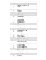
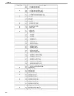
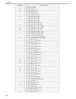
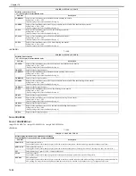
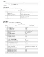
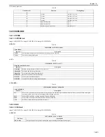
(2) Numeric parameter
T-16-58
16.5 TESTMODE
16.5.1 SYSTEM
16.5.1.1 SYSTEM List
0020-2024
imageCLASS MF9170c / imageCLASS MF9150c / imageCLASS MF8450c
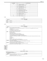
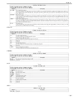
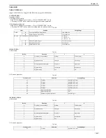
<DRAM>
T-16-59
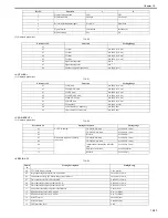
<ACC>
T-16-60
<SPEAKER>
T-16-61
16.5.2 SCAN
16.5.2.1 SCAN List
0020-2025
imageCLASS MF9170c / imageCLASS MF9150c / imageCLASS MF8450c
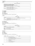
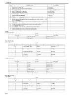
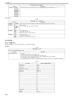
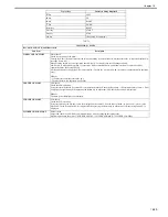
<ADJUST>
T-16-62
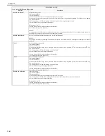
Parameter No.
Function
Setting Range
01
02
T1 timer
0 to 9999 (x 10 ms)
03
T2 timer
0 to 9999 (x 10 ms)
04
T3 timer
0 to 9999 (x 10 ms)
05
T4 timer
0 to 9999 (x 10 ms)
06
Signal sensing table
0 to 16
07
Signal sensing level
0 to 9
08
Number of signal frequencies
0 to 9999 (pce)
TESTMODE > SYSTEM > DRAM
Check DRAM
Sub item
Description
TEST1
Check writing/reading of data in DRAM area (excluding system work area)
TEST2
Check data reading (high speed)
TESTMODE > SYSTEM > ACC
Check ID control card reader
Sub item
Description
NCR-CRD
Display: presence/absence of NCR device or the card
CRD-KIND
Card type (the first 3-digit characters)
CRD-STYL
Card format (the second 3-digit characters)
READ-STS
Read status (the third 3/2-digit characters)
NCR-STS
Device status (the fourth character)
NCR-VER
Version of NCR device (4-digit numeric figures)
TESTMODE > SYSTEM > SPEAKER
Check SPEAKER
Sub item
Description
ON
When "ON" is selected, increase the volume step by step from the minimum up to maximum whenever OK key is pressed. When reaching the
maximum volume, it goes back to the minimum volume through silent state.
MIN
When "MIN" is selected, set off the minimum volume with OK key.
MAX
When "MAX" is selected, set off the maximum volume with OK key.
VOL
Set off the volume according to the hardware volume.
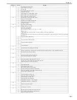
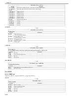
TESTMODE > SCAN > ADJUST
Sub item
Description
WLVL-ADJ
Correct white level in copyboard scanning and stream scanning to determine shading target.
Summary of Contents for imageCLASS MF8450c
Page 16: ...Chapter 1 Introduction ...
Page 55: ...Chapter 2 Basic Operation ...
Page 61: ...Chapter 3 Main Controller ...
Page 75: ...Chapter 4 Original Exposure System ...
Page 88: ...Chapter 5 Original Feeding System ...
Page 105: ...Chapter 6 Laser Exposure ...
Page 113: ...Chapter 7 Image Formation ...
Page 150: ...Chapter 8 Pickup and Feed System ...
Page 184: ...Chapter 9 Fixing System ...
Page 200: ...Chapter 10 External and Controls ...
Page 230: ...Chapter 11 Maintenance and Inspection ...
Page 233: ...Chapter 12 Measurement and Adjustments ...
Page 237: ...Chapter 13 Correcting Faulty Images ...
Page 260: ...Chapter 14 Error Code ...
Page 272: ...Chapter 15 Special Management Mode ...
Page 280: ...Chapter 16 Service Mode ...
Page 322: ...Chapter 17 Upgrading ...
Page 327: ...Chapter 17 17 4 3 Click Next F 17 4 4 Select a USB connected device and click Next F 17 5 ...
Page 328: ...Chapter 17 17 5 5 Click Start F 17 6 6 Click Yes F 17 7 Download will be started F 17 8 ...
Page 330: ...Chapter 18 Service Tools ...
Page 334: ...Appendix ...
Page 349: ......

