Chapter 3
3-12
3.5 Parts Replacement Procedure
3.5.1 Main Controller PCB
3.5.1.1 Before Removing the Main Controller PCB
0020-3324
imageCLASS MF9170c / imageCLASS MF9150c / imageCLASS MF8450c
1) Remove the ETB unit.
Reference [Removing the ETB Unit]
2) Remove the rear cover unit.
Reference [Removing the Rear
Cover Unit]
3) Remove the left cover.
Reference [Removing the Left Cov-
er]
4) Remove the right cover.
Reference [Removing the Right
Cover]
5) Remove the Electrical Components Cover.
Reference [Re-
moving the Electrical Components Cover]
6) Remove the Controller Box.
Reference [Removing the Con-
troller Box]
3.5.1.2 Removing the Main Controller PCB
0020-3325
imageCLASS MF9170c / imageCLASS MF9150c / imageCLASS MF8450c
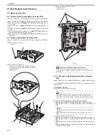
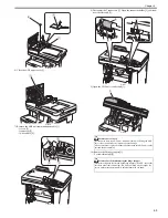
1) Remove the face cover [1].
- 1 screw [2]
F-3-15
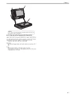
2) Remove the NCU frame [1].
- 1 flat cable [2] (only of the machine with FAX)
- 1 connectors [3] (only of the machine with FAX)
- 1 connectors [4]
- 6 screws [5]
F-3-16
3) Remove the Main controller PCB [1].
- 2 connectors [2]
- 10 screws [3]
F-3-17
T-3-4
3.5.1.3 Procedure after Replacing the Main Controller
PCB
0021-0348
imageCLASS MF9170c / imageCLASS MF9150c / imageCLASS MF8450c
After replacing the main controller PCB with new one, perform the follow-
ing procedure.
1. Backup the user data
Import the user data using the remote UI.
2. Enter the flicker adjustment value of the control panel
1) Using the service mode, check the flicker value of the control panel.
TESTMODE> PANEL> FLICKER CHECK START> FLICKER AD-
JUST
2) Replace the main controller PCB.
3) Using the service mode, enter the adjustment value checked in Step 1).
TESTMODE> PANEL> FLICKER CHECK START> FLICKER AD-
JUST
4) Using the user mode, execute automatic gradation correction (full correc-
tion).
Initial Setting/Registration> Adjustment/Cleaning> Automatic Gradation
Correction> Full Correction
[1]
[2]
[1]
[2]
[4]
[3]
[5]
[5]
[5]
Points to Note When Replacing the Main Controller
- If the RAM [4] is installed in the main controller PCB, remove it.
- If a RAM is not installed in the new main controller, install the removed
RAM [4].
The machine does not support "Import/export via USB" (provided in the
following service SW) because it supports network as standard function.
# COPIER->FUNCTION->PARAM->SYS-SW->Bit Switch->SW 02 Bit6
MEMO:
The flicker adjustment value can be also checked in the spec list (FLICKER
ADJ PRM).
How to output the spec list: COPIER> FUNCTION> MISC-P> OUTPUT>
SPEC
[2]
[3]
[3]
[1]
[4]
Summary of Contents for imageCLASS MF8450c
Page 16: ...Chapter 1 Introduction ...
Page 55: ...Chapter 2 Basic Operation ...
Page 61: ...Chapter 3 Main Controller ...
Page 75: ...Chapter 4 Original Exposure System ...
Page 88: ...Chapter 5 Original Feeding System ...
Page 105: ...Chapter 6 Laser Exposure ...
Page 113: ...Chapter 7 Image Formation ...
Page 150: ...Chapter 8 Pickup and Feed System ...
Page 184: ...Chapter 9 Fixing System ...
Page 200: ...Chapter 10 External and Controls ...
Page 230: ...Chapter 11 Maintenance and Inspection ...
Page 233: ...Chapter 12 Measurement and Adjustments ...
Page 237: ...Chapter 13 Correcting Faulty Images ...
Page 260: ...Chapter 14 Error Code ...
Page 272: ...Chapter 15 Special Management Mode ...
Page 280: ...Chapter 16 Service Mode ...
Page 322: ...Chapter 17 Upgrading ...
Page 327: ...Chapter 17 17 4 3 Click Next F 17 4 4 Select a USB connected device and click Next F 17 5 ...
Page 328: ...Chapter 17 17 5 5 Click Start F 17 6 6 Click Yes F 17 7 Download will be started F 17 8 ...
Page 330: ...Chapter 18 Service Tools ...
Page 334: ...Appendix ...
Page 349: ......

