Chapter 10
10-1
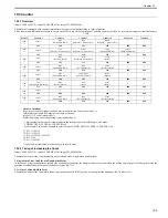
10.1 DC Controller
10.1.1 Overview
0020-2652
imageCLASS MF9170c / imageCLASS MF9150c / imageCLASS MF8450c
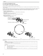
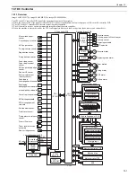
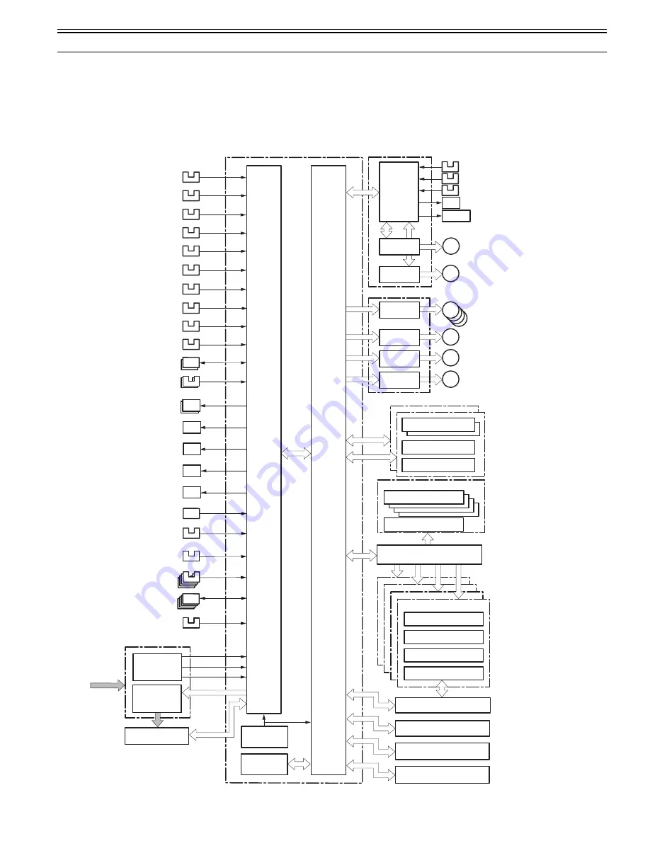
The CPU in the DC controller PCB controls the operational sequence of the machine.
1) When the power switch of the machine is turned ON, DC power is supplied from the low-voltage power PCB to the DC controller PCB.
2) The CPU in the DC controller PCB starts to control the printer operation.
3) The DC controller receives a print command and image data from the main controller.
4) When the machine is placed in standby, the CPU sends signals to drive each load, such as laser diode, motors, and solenoids, etc.
F-10-1
Driver PCB
DC controller PCB
Cassette paper sensor
Manual feed paper
sensor
ADF paper sensor
Registration sensor
+3.3V
+5V
+24V
AC input
IC1007
EEPROM
IC1002
Reset IC
Drum motors
Paper displacement
sensor
Paper loop sensor
Pre-registration sensor
M
M
Duplexing feed motor
Color displacement
/density sensors
Developing
disengagement solenoids
manual pickup solenoid
Cassette pickup solenoid
ETB disengagement
solenoid
Low-voltage power PCB
Fixing delivery sensor
ADF paper trailing edge
sensor
M
ETB motor
Reverse motor
M
M
Fixing motor
Pickup motor
Environment sensor
Fixing pressure release
sensor
Front cover sensor
Drum HP sensors
Toner level detection
assembly
ADF pickup solenoid
Laser scanner units
BD circuit
Laser driver
New cartridge sensor
Reader HP sensor
SL
Fixing
control
circuit
M
Low-voltage
power circuit
SL
SL
SL
SL
IC801
DUPLEX
CPU
SL
FAN
IC802
Reverse sensor
Delivery sensor
Delivery paper full-level sensor
Duplexing solenoid
Duplex fan
Developing
disengagement sensors
Reverse driver PCB
IC803
Attraction roller
Primary charging rollers
Developing cylinders
Photosensitive drums
Memory tags
High-voltage power PCB
Transfer rollers
ETB unit
Toner cartridges
CPU
(IC1001)
Fixing unit
Main unit fan
IC401
ASIC
(IC1010)
Memory controller PCB
Main controller PCB
ADF
Scanner motors
Summary of Contents for imageCLASS MF8450c
Page 16: ...Chapter 1 Introduction ...
Page 55: ...Chapter 2 Basic Operation ...
Page 61: ...Chapter 3 Main Controller ...
Page 75: ...Chapter 4 Original Exposure System ...
Page 88: ...Chapter 5 Original Feeding System ...
Page 105: ...Chapter 6 Laser Exposure ...
Page 113: ...Chapter 7 Image Formation ...
Page 150: ...Chapter 8 Pickup and Feed System ...
Page 184: ...Chapter 9 Fixing System ...
Page 200: ...Chapter 10 External and Controls ...
Page 230: ...Chapter 11 Maintenance and Inspection ...
Page 233: ...Chapter 12 Measurement and Adjustments ...
Page 237: ...Chapter 13 Correcting Faulty Images ...
Page 260: ...Chapter 14 Error Code ...
Page 272: ...Chapter 15 Special Management Mode ...
Page 280: ...Chapter 16 Service Mode ...
Page 322: ...Chapter 17 Upgrading ...
Page 327: ...Chapter 17 17 4 3 Click Next F 17 4 4 Select a USB connected device and click Next F 17 5 ...
Page 328: ...Chapter 17 17 5 5 Click Start F 17 6 6 Click Yes F 17 7 Download will be started F 17 8 ...
Page 330: ...Chapter 18 Service Tools ...
Page 334: ...Appendix ...
Page 349: ......

