Chapter 3
3-5
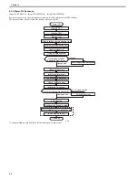
3.2.2 Startup Sequence
0020-8295
imageCLASS MF9170c / imageCLASS MF9150c / imageCLASS MF8450c
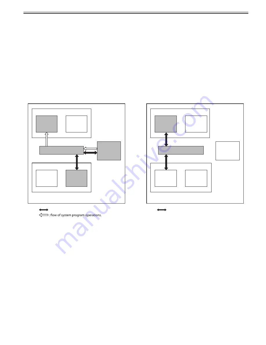
1. Boot Program
Executed by the CPU in the main controller PCB when the main power switch is turned on.
Check the status of the image memory (DDR-SDRAM).
Load the control program from the main program ROM to the memory if the status is normal.
Display an error code when a fault is detected.
2. Control Program 1
1) Perform checking and initialization of each device (each hardware device in the main controller PCB).
2) Perform recovery of the system file as necessary when the previous shutdown was not executed normally.
In this case, it takes longer time than a normal case to start up the program.
3) Initialize each program module.
3. Control Program 2
1) Perform initialization of each software module and communication with a printer.
2) When the printer is detected normally, the startup sequence is completed.
If it is not detected normally, an error code "E197" is displayed after a connection timeout occurs.
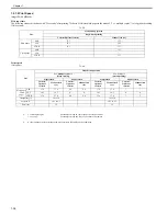
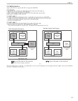
F-3-4
When the startup sequence is completed, it becomes possible to receive a job. (The operation screen is displayed in the control panel, and the color of the LED of
the start key is changed from red to green.)
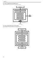
CPU
BootROM
Main controller PCB
: access to the program at time of execution.
- When Executing the Boot Program
Main program
ROM
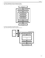
CPU
: access to the program at time of execution.
- When Executing the Control Program
Image memory (DDR-SD
RAM)
System
area
Image data
area
Self
diagnostic
program
Boot
program
System
software
BootROM
Main program
ROM
Image memory (DDR-SD
RAM)
System
area
Image data
area
Self
diagnostic
program
Boot
program
System
software
Summary of Contents for imageCLASS MF8450c
Page 16: ...Chapter 1 Introduction ...
Page 55: ...Chapter 2 Basic Operation ...
Page 61: ...Chapter 3 Main Controller ...
Page 75: ...Chapter 4 Original Exposure System ...
Page 88: ...Chapter 5 Original Feeding System ...
Page 105: ...Chapter 6 Laser Exposure ...
Page 113: ...Chapter 7 Image Formation ...
Page 150: ...Chapter 8 Pickup and Feed System ...
Page 184: ...Chapter 9 Fixing System ...
Page 200: ...Chapter 10 External and Controls ...
Page 230: ...Chapter 11 Maintenance and Inspection ...
Page 233: ...Chapter 12 Measurement and Adjustments ...
Page 237: ...Chapter 13 Correcting Faulty Images ...
Page 260: ...Chapter 14 Error Code ...
Page 272: ...Chapter 15 Special Management Mode ...
Page 280: ...Chapter 16 Service Mode ...
Page 322: ...Chapter 17 Upgrading ...
Page 327: ...Chapter 17 17 4 3 Click Next F 17 4 4 Select a USB connected device and click Next F 17 5 ...
Page 328: ...Chapter 17 17 5 5 Click Start F 17 6 6 Click Yes F 17 7 Download will be started F 17 8 ...
Page 330: ...Chapter 18 Service Tools ...
Page 334: ...Appendix ...
Page 349: ......

