Chapter 14
14-3
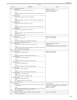
T-14-3
Code
Description
Action
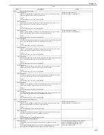
E012
Error in activation of motor
0000 Description
When 3.5 sec passed after activation of ETB motor, the cycle of ETB motor speed
detection signal does not become its specified value.
Cause
Error in ETB motor, error in DC controller PCB.
- Replacement of ETB motor
- Replacement of DC controller PCB
0001 Description
After ETB motor speed detection signal became the specified value of the cycle, it
exceeds the specified cycle for 2 continuous sec or more.
Cause
Error in ETB motor, error in DC controller PCB.
0002 Description
When 2.5 sec passed after activation of the yellow drum motor, the cycle of drum
motor speed detection signal does not become its specified value.
Cause
Error in drum motor, error in DC controller PCB.
- Replacement of drum motor
- Replacement of DC controller PCB
0003 Description
After the yellow drum motor speed detection signal became the specified value of the
cycle, it exceeds the specified cycle for 2 continuous sec or more.
Cause
Error in drum motor, error in DC controller PCB.
0004 Description
When 2.5 sec passed after activation of the magenta drum motor, the cycle of drum
motor speed detection signal does not become its specified value.
Cause
Error in drum motor, error in DC controller PCB.
0005 Description
After the magenta drum motor speed detection signal became the specified value of the
cycle, it exceeds the specified cycle for 2 continuous sec or more.
Cause
Error in drum motor, error in DC controller PCB.
0006 Description
When 2.5 sec passed after activation of the cyan drum motor, the cycle of the drum
motor speed detection signal does not become its specified value.
Cause
Error in drum motor, error in DC controller PCB.
0007 Description
After the cyan drum motor speed detection signal became the specified value of the
cycle, it exceeds the specified cycle for 2 continuous sec or more.
Cause
Error in drum motor, error in DC controller PCB.
0008 Description
When 2.5 sec passed after activation of the black drum motor, the cycle of the drum
motor speed detection signal does not become its specified value.
Cause
Error in drum motor, error in DC controller PCB.
0009 Description
After the black drum motor speed detection signal became the specified value of the
cycle, it exceeds the specified cycle for 2 continuous sec or more.
Cause
Error in drum motor, error in DC controller PCB.
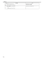
E014
Error in activation of fixing motor
0000 Description
When 2.5 sec passed after activation of fixing motor, the cycle of the fixing motor
speed detection signal does not become its specified value.
Cause
Error in fixing motor, error in DC controller PCB.
- Replacement of fixing motor
- Replacement of DC controller PCB
0001 Description
After the fixing motor speed detection signal became the specified value of the cycle,
it exceeds the specified cycle for 2 continuous sec or more.
Cause
Error in fixing motor, error in DC controller PCB.
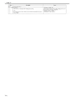
E015
Failure in developing disengagement
0000 Description
Developing cylinder disengagement mechanism does not function correctly.
Cause
Developing disengagement mechanism fault, developing disengagement solenoid
fault, developing disengagement sensor fault, DC controller PCB fault.
Check the developing disengagement mechanism.
Replace developing disengagement solenoid.
Replace developing disengagement sensor.
Replace DC controller PCB.
Summary of Contents for imageCLASS MF8450c
Page 16: ...Chapter 1 Introduction ...
Page 55: ...Chapter 2 Basic Operation ...
Page 61: ...Chapter 3 Main Controller ...
Page 75: ...Chapter 4 Original Exposure System ...
Page 88: ...Chapter 5 Original Feeding System ...
Page 105: ...Chapter 6 Laser Exposure ...
Page 113: ...Chapter 7 Image Formation ...
Page 150: ...Chapter 8 Pickup and Feed System ...
Page 184: ...Chapter 9 Fixing System ...
Page 200: ...Chapter 10 External and Controls ...
Page 230: ...Chapter 11 Maintenance and Inspection ...
Page 233: ...Chapter 12 Measurement and Adjustments ...
Page 237: ...Chapter 13 Correcting Faulty Images ...
Page 260: ...Chapter 14 Error Code ...
Page 272: ...Chapter 15 Special Management Mode ...
Page 280: ...Chapter 16 Service Mode ...
Page 322: ...Chapter 17 Upgrading ...
Page 327: ...Chapter 17 17 4 3 Click Next F 17 4 4 Select a USB connected device and click Next F 17 5 ...
Page 328: ...Chapter 17 17 5 5 Click Start F 17 6 6 Click Yes F 17 7 Download will be started F 17 8 ...
Page 330: ...Chapter 18 Service Tools ...
Page 334: ...Appendix ...
Page 349: ......

