Chapter 6
6-6
6.4 Parts Replacement Procedure
6.4.1 Laser/Scanner Unit
6.4.1.1 Before Removing the Laser Scanner Unit
0020-3356
imageCLASS MF9170c / imageCLASS MF9150c / imageCLASS MF8450c
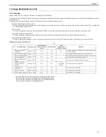
1) Remove the ETB unit.
Reference [Removing the ETB Unit]
2) Remove the rear cover unit.
Reference [Removing the Rear
Cover Unit]
3) Remove the left cover.
Reference [Removing the Left Cov-
er]
4) Remove the right cover.
Reference [Removing the Right
Cover]
5) Remove the Electrical Components Cover.
Reference [Re-
moving the Electrical Components Cover]
6) Remove the Controller Box.
Reference [Removing the Con-
troller Box]
7) Remove the Off Hook PCB. (only of the machine with FAX)
Reference [Removing the Off Hook PCB]
8) Remove the DC Controller PCB.
Reference [Removing the
DC Controller PCB]
9) Remove the Laser Scanner Cover.
Reference [Removing the
Laser Scanner Cover]
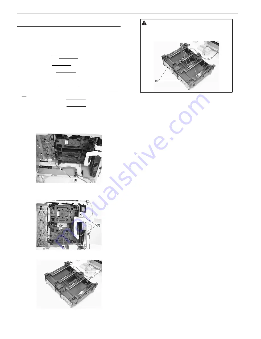
6.4.1.2 Removing the Laser Scanner Unit
0018-9193
imageCLASS MF9170c / imageCLASS MF9150c / imageCLASS MF8450c
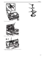
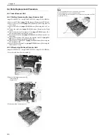
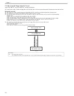
1) Free the cable from the wire saddle [1].
F-6-5
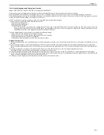
2) Remove the laser scanner unit [1].
- 2 flat cables [2]
- 5 screws [3]
F-6-6
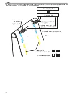
3) Disconnect the 2 connectors [1]
F-6-7
- Do not disassemble the laser scanner unit in the field.
Disassembling it may cause a functional fault.
- When holding the laser scanner unit, be careful not to touch the laser PCB
[1] and the lens [2].
Summary of Contents for imageCLASS MF8450c
Page 16: ...Chapter 1 Introduction ...
Page 55: ...Chapter 2 Basic Operation ...
Page 61: ...Chapter 3 Main Controller ...
Page 75: ...Chapter 4 Original Exposure System ...
Page 88: ...Chapter 5 Original Feeding System ...
Page 105: ...Chapter 6 Laser Exposure ...
Page 113: ...Chapter 7 Image Formation ...
Page 150: ...Chapter 8 Pickup and Feed System ...
Page 184: ...Chapter 9 Fixing System ...
Page 200: ...Chapter 10 External and Controls ...
Page 230: ...Chapter 11 Maintenance and Inspection ...
Page 233: ...Chapter 12 Measurement and Adjustments ...
Page 237: ...Chapter 13 Correcting Faulty Images ...
Page 260: ...Chapter 14 Error Code ...
Page 272: ...Chapter 15 Special Management Mode ...
Page 280: ...Chapter 16 Service Mode ...
Page 322: ...Chapter 17 Upgrading ...
Page 327: ...Chapter 17 17 4 3 Click Next F 17 4 4 Select a USB connected device and click Next F 17 5 ...
Page 328: ...Chapter 17 17 5 5 Click Start F 17 6 6 Click Yes F 17 7 Download will be started F 17 8 ...
Page 330: ...Chapter 18 Service Tools ...
Page 334: ...Appendix ...
Page 349: ......

