Chapter 7
7-13
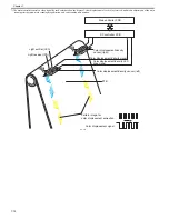
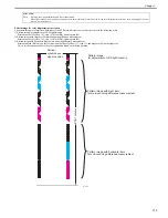
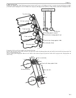
Pattern image for color displacement correction
The pattern images are formed on both sides of the ETB certain distance away from the center in the following order.
1) Pattern image for adjustment of LED light intensity
Printed in order of yellow (Y), cyan (C), black (Bk), and magenta (M).
2) Pattern image with slant bars for main-scanning difference measurement
Printed in order of yellow (Y), cyan (C), black (Bk), and magenta (M).
3) Pattern image with horizontal bars for sub-scanning difference measurement
Printed in black (Bk) only on the left side, and in order of yellow (Y), cyan (C), and magenta (M) on the right side.
This is for the comparison of each color registration based on the black position.
F-7-17
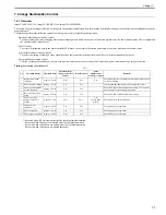
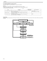
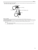
Error Codes:
E020
Warning: color displacement/density sensor abnormality
When light could not be received by the light receiver, the machine sets an initial value for the color displacement corrective value, and displays the error
code on the control panel.
Pattern image
for adjustment of LED light intensity
Pattern image with slant bars
for main-scanning difference measurement
Pattern image with horizontal bars
for sub-scanning difference measurement
Vertical
synchronous
signal position
ETB 1 rotation
Summary of Contents for imageCLASS MF8450c
Page 16: ...Chapter 1 Introduction ...
Page 55: ...Chapter 2 Basic Operation ...
Page 61: ...Chapter 3 Main Controller ...
Page 75: ...Chapter 4 Original Exposure System ...
Page 88: ...Chapter 5 Original Feeding System ...
Page 105: ...Chapter 6 Laser Exposure ...
Page 113: ...Chapter 7 Image Formation ...
Page 150: ...Chapter 8 Pickup and Feed System ...
Page 184: ...Chapter 9 Fixing System ...
Page 200: ...Chapter 10 External and Controls ...
Page 230: ...Chapter 11 Maintenance and Inspection ...
Page 233: ...Chapter 12 Measurement and Adjustments ...
Page 237: ...Chapter 13 Correcting Faulty Images ...
Page 260: ...Chapter 14 Error Code ...
Page 272: ...Chapter 15 Special Management Mode ...
Page 280: ...Chapter 16 Service Mode ...
Page 322: ...Chapter 17 Upgrading ...
Page 327: ...Chapter 17 17 4 3 Click Next F 17 4 4 Select a USB connected device and click Next F 17 5 ...
Page 328: ...Chapter 17 17 5 5 Click Start F 17 6 6 Click Yes F 17 7 Download will be started F 17 8 ...
Page 330: ...Chapter 18 Service Tools ...
Page 334: ...Appendix ...
Page 349: ......


