Chapter 16
16-39
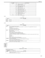
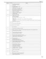
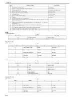
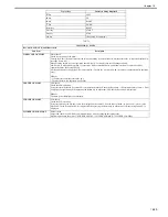
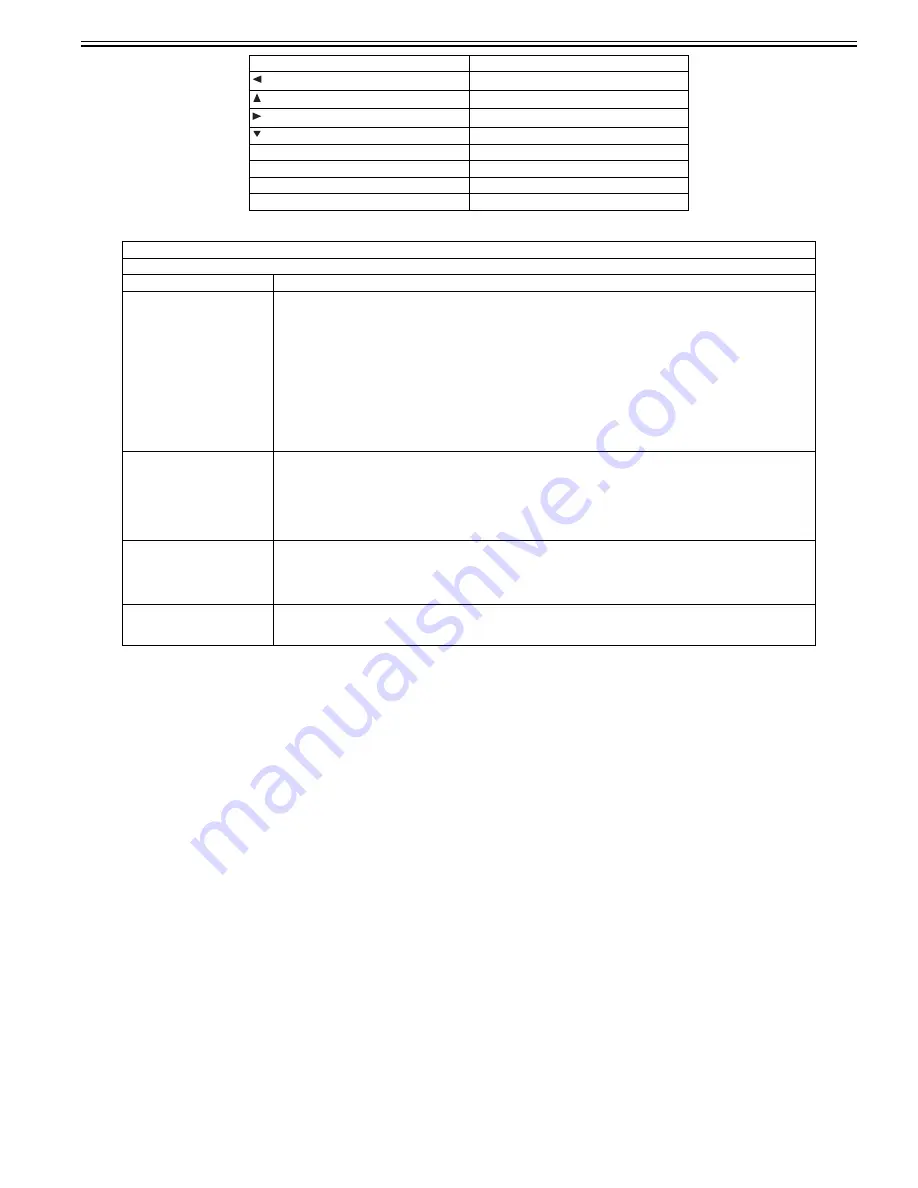
T-16-71
key
LEFT
key
UP
key
RIGHT
key
DOWN
Reset key
RESET
Start key
START
Stop key
STOP
OK key
(Key check is completed.)
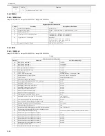
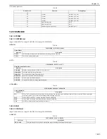
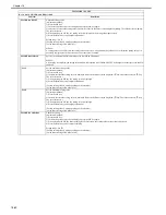
TESTMODE > PANEL
Key, wheel, LCD, LED, and flicker check
Sub item
Description
WHEEL CHECK START
Wheel check
Check the operation of the wheel.
Turning the wheel clockwise increases the value, and turning it counterclockwise decreases the value. (Values are displayed in
the range from 0 to 23.)
When pressing the OK key after operation check, OK or NG is displayed in the following condition.
OK: Entry was made with more than 12 consecutive clicks counterclockwise, and with more than 12 consecutive clicks
counterclockwise. (Refer to MEMO.)
NG: Requirements for displaying OK are not satisfied. (The OK key was pressed with clockwise or counterclockwise operation
only.)
MEMO:
- 1 click increases/decreases the value by 1.
- The wheel rotates 360 degrees with 24 clicks.
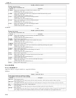
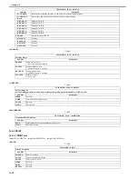
LED CHECK START
LED check
Check the LED operation.
Every time pressing the OK key after LEDs are completely turned off, the Start Key Lamp --> Execution/Memory Lamp --> Error
Lamp light up sequentially. When pressing the Return key in midstream, LED check stops and NG is displayed.
MEMO:
The main power lamp lights up constantly.
LCD CHECK START
LCD check
Check the LCD operation.
Every time pressing the OK key, colors are displayed on the entire LCD in the order of black-->white-->red-->green-->blue.
When LED check is completed, OK is displayed. When pressing the Return key in midstream, LCD check stops and NG is
displayed.
FLICKER CHECK START
Flicker check
Adjust and check the LCD flicker. Adjustment can be made by changing the setting value.
Perform operation in the order of "FLICKER ADJUST -> FLICEKR MIN/MAX -> FLICKER CONFIRM".
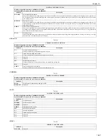
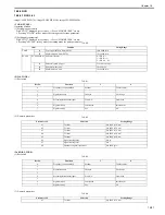
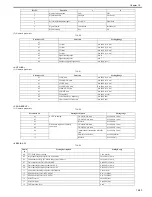
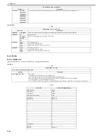
Type of Key
Character String Displayed
Summary of Contents for imageCLASS MF8450c
Page 16: ...Chapter 1 Introduction ...
Page 55: ...Chapter 2 Basic Operation ...
Page 61: ...Chapter 3 Main Controller ...
Page 75: ...Chapter 4 Original Exposure System ...
Page 88: ...Chapter 5 Original Feeding System ...
Page 105: ...Chapter 6 Laser Exposure ...
Page 113: ...Chapter 7 Image Formation ...
Page 150: ...Chapter 8 Pickup and Feed System ...
Page 184: ...Chapter 9 Fixing System ...
Page 200: ...Chapter 10 External and Controls ...
Page 230: ...Chapter 11 Maintenance and Inspection ...
Page 233: ...Chapter 12 Measurement and Adjustments ...
Page 237: ...Chapter 13 Correcting Faulty Images ...
Page 260: ...Chapter 14 Error Code ...
Page 272: ...Chapter 15 Special Management Mode ...
Page 280: ...Chapter 16 Service Mode ...
Page 322: ...Chapter 17 Upgrading ...
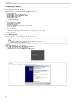
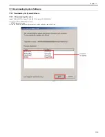
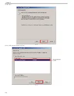
Page 327: ...Chapter 17 17 4 3 Click Next F 17 4 4 Select a USB connected device and click Next F 17 5 ...
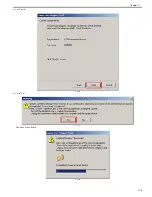
Page 328: ...Chapter 17 17 5 5 Click Start F 17 6 6 Click Yes F 17 7 Download will be started F 17 8 ...
Page 330: ...Chapter 18 Service Tools ...
Page 334: ...Appendix ...
Page 349: ......

