Chapter 14
14-8
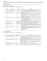
14.3 Jam Code
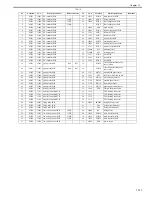
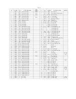
14.3.1 Jam Code (main body)
0020-4442
imageCLASS MF9170c / imageCLASS MF9150c / imageCLASS MF8450c
T-14-6
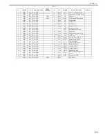
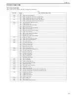
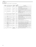
14.3.2 Jam Code (ADF)
0020-4444
imageCLASS MF9170c / imageCLASS MF9150c / imageCLASS MF8450c
T-14-7
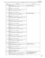
Code Name Sensor
No.
Description
0104
Delay jam in paper pickup section
SR710
The registration sensor cannot detect the leading edge of paper from the moment paper
pickup starts to the moment the jam detection time is reached.
0208
Stationary jam in paper pickup section
SR710
The registration sensor cannot detect the no paper status specified time before the leading
edge of the picked up paper reaches this sensor.
010c
Delay jam in deliver section
SR710, SR6005
- The fixing delivery sensor cannot detect presence of paper within the specified time after
turning on of the registration clutch.
- The fixing delivery sensor detected absence of paper within the specified time after the
sensor had detected presence of paper within the specified time after turning on of the
registration clutch.
- The No.1 delivery sensor cannot detect presence of paper within the specified time after
turning on of the fixing delivery sensor.
0210
Stationary jam in delivery section
SR710, SR6005
- The fixing delivery sensor cannot detect absence of paper within the specified time after
turning off of the registration clutch.
- The fixing delivery sensor cannot detect absence of paper within the specified time after
the sensor detected the leading edge of paper.
- The No.1 delivery sensor cannot detect absence of paper within the specified time after the
sensor detected the leading edge of paper.
0214
Stationary jam in machine
SR706, SR710,
SR6001, SR6005
Paper was detected in the paper transport path during initial rotation, during automatic
delivery, at the end of cleaning, or at reception of an emergency stop command.
1118
Door open jam
SR720
The door was opened when there was printing paper in the transport path.
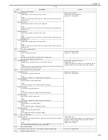
0221
Reverse section JAM
SR706, SR715
This jam is applied when the double-fed paper drops on the back of the host machine.
The machine determines the reverse section jam if the paper length that is detected by the
reverse sensor (SR706) is 50mm or more longer than the paper length that is detected by the
delivery sensor (SR715).
0228
Reverse re-pickup section jam
SR710
The machine determines the reverse re-pickup jam if the registration sensor (SR710) cannot
detect the presence of paper within the specified time (t) after the duplexing pickup starts.
Specified time (t) differs depending on the feeding speed.
1/1 speed: approx. 2.0 sec
4/5 speed: approx. 2.5 sec
1/2 speed: approx 4.0 sec
Code Name Sensor
No.
Description
0001
ADF paper trailing edge sensor (SR719)
not reaching (delay jam)
SR719
The leading edge of paper does not reach the ADF paper trailing edge sensor (SR719) within
1.8 sec after the trailing edge of precedent page passes through the ADF paper trailing edge
sensor (SR719) in 1-sided multiple jobs.
The leading edge of paper does not reach the ADF paper trailing edge sensor (SR719) within
1.2 sec after reverse operation starts in 2-sided job.
0002
ADF paper trailing edge sensor (SR719)
stray (stray jam)
SR719
The trailing edge of paper does not passes through the ADF paper trailing edge sensor (SR719)
within 3.4 sec after the leading edge of paper reaches the ADF paper trailing edge sensor
(SR719) in 1-sided job.
The trailing edge of paper does not passes through the ADF paper trailing edge sensor (SR719)
within 3.5 sec after the leading edge of paper reaches the ADF paper trailing edge sensor
(SR719) in 2-sided job.
0094
Initial stationary (in-body residual jam) SR719
The ADF paper trailing edge sensor (SR719) detects paper at power-ON.
0095
Pickup NG
SR718
The paper is removed from the ADF original tray within 0.1 sec after the start key is pressed.
Summary of Contents for imageCLASS MF8450c
Page 16: ...Chapter 1 Introduction ...
Page 55: ...Chapter 2 Basic Operation ...
Page 61: ...Chapter 3 Main Controller ...
Page 75: ...Chapter 4 Original Exposure System ...
Page 88: ...Chapter 5 Original Feeding System ...
Page 105: ...Chapter 6 Laser Exposure ...
Page 113: ...Chapter 7 Image Formation ...
Page 150: ...Chapter 8 Pickup and Feed System ...
Page 184: ...Chapter 9 Fixing System ...
Page 200: ...Chapter 10 External and Controls ...
Page 230: ...Chapter 11 Maintenance and Inspection ...
Page 233: ...Chapter 12 Measurement and Adjustments ...
Page 237: ...Chapter 13 Correcting Faulty Images ...
Page 260: ...Chapter 14 Error Code ...
Page 272: ...Chapter 15 Special Management Mode ...
Page 280: ...Chapter 16 Service Mode ...
Page 322: ...Chapter 17 Upgrading ...
Page 327: ...Chapter 17 17 4 3 Click Next F 17 4 4 Select a USB connected device and click Next F 17 5 ...
Page 328: ...Chapter 17 17 5 5 Click Start F 17 6 6 Click Yes F 17 7 Download will be started F 17 8 ...
Page 330: ...Chapter 18 Service Tools ...
Page 334: ...Appendix ...
Page 349: ......

