Chapter 3
3-3
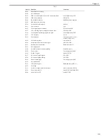
T-3-3
Jack No.
Function
Connect to
J8101
Serial interface for debug
-
J8102
Not implemented
-
J8103
USB on a control panel, Connect to a media card reader
Control panel relay PCB
J8104
USB device connector
USB device
J8106
RAM DIMM connector
RAM DIMM for expansion
J8109
SRAM connector for debug
-
J8110
On-board SD card interface
SD card
J8111
LAN connector
LAN
J8112
Video signal, engine command
DC controller PCB
J8113
CCD read image signal, lamp power/control signal
CCD relay PCB
J8114
Control panel screen image signal, key signal
Control panel relay PCB
J8117
CCVI interface
CC-VI
J8118
Serial interface
Coin vendor (100V, 230V)
Serial I/F PCB (120V)
J8119
Card reader interface
Card reader-E1
J8120
Motor for ADF, solenoid, sensor signal
ADF relay PCB
J8121
Reader motor control signal
Reader motor (M12)
J8123
Not implemented
-
J8124
Secondary battery for memory backup
Secondary battery
J8125
Power source
Low-voltage power PCB
J8126
Pseudo CI signal
Pseudo CI PCB
J8127
NCU control signal (digital)
NCU PCB
J8128
NCU control signal (analog)
NCU PCB
J8129
Power control signal
Low-voltage power PCB
J8130
Not implemented
-
J8131
CCD unit HP signal
Reader HP sensor (SR717)
J8132
For debug
-
J8133
Front cover open/close detection signal
Front cover sensor (SR720)
J8134
Power for pseudo CI
Pseudo CI PCB/off hook PCB
J8140
Power for serial I/F
Serial I/F PCB
Summary of Contents for imageCLASS MF8450c
Page 16: ...Chapter 1 Introduction ...
Page 55: ...Chapter 2 Basic Operation ...
Page 61: ...Chapter 3 Main Controller ...
Page 75: ...Chapter 4 Original Exposure System ...
Page 88: ...Chapter 5 Original Feeding System ...
Page 105: ...Chapter 6 Laser Exposure ...
Page 113: ...Chapter 7 Image Formation ...
Page 150: ...Chapter 8 Pickup and Feed System ...
Page 184: ...Chapter 9 Fixing System ...
Page 200: ...Chapter 10 External and Controls ...
Page 230: ...Chapter 11 Maintenance and Inspection ...
Page 233: ...Chapter 12 Measurement and Adjustments ...
Page 237: ...Chapter 13 Correcting Faulty Images ...
Page 260: ...Chapter 14 Error Code ...
Page 272: ...Chapter 15 Special Management Mode ...
Page 280: ...Chapter 16 Service Mode ...
Page 322: ...Chapter 17 Upgrading ...
Page 327: ...Chapter 17 17 4 3 Click Next F 17 4 4 Select a USB connected device and click Next F 17 5 ...
Page 328: ...Chapter 17 17 5 5 Click Start F 17 6 6 Click Yes F 17 7 Download will be started F 17 8 ...
Page 330: ...Chapter 18 Service Tools ...
Page 334: ...Appendix ...
Page 349: ......

